background image

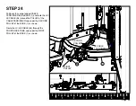
SECURELY

 assemble the RIGHT DOOR

SHROUD 

(WITH “T” LOGO)

 (30) to the RIGHT

DOOR (6) using:

Eight 1/4 X 1/2" BOLTS (49)
Eight 1/4” WASHERS (50)

SECURELY

 assemble the LEFT DOOR

SHROUD 

(WITH STAND OFF)

 (31) to the LEFT

DOOR (8) using:

Eight 1/4 X 1/2" BOLTS (49)
Eight 1/4” WASHERS (50)

Remove the backing from the F3 PLACARD
(44) and attach it to the STAND OFF on the
LEFT DOOR (8) as shown.

Page


34

1

2

3

4

5

6

STEP


28

1

/

4


X


1/2

” 

49

50

6

30

8

31

44

F3 PLACARD

Summary of Contents for Fold Away Strength Trainer F3

Page 1: ...Part 5134001 C Version F3 01 001 Assembly and Maintenance Guide Fold Away Strength Trainer TM ...

Page 2: ...btaining Service 3 General Notes 4 Unpacking the Equipment 4 Tools Required 4 Optional Equipment 4 Assembly Tips 4 Parts List 5 6 Assembly Instructions 6 36 Adjustments and Maintenance 32 36 CableAdjustments 32 Attachment andAdjustment Instructions 35 Maintenance 36 Assembly Checklist 38 Warranty Statement 40 41 Warranty Registration 43 44 TABLE OF CONTENTS ...

Page 3: ... impair freedom of movement Do not wear clothing which is too loose and could get caught in moving parts 6 Make sure all adjustment spring pins are fully engaged after making an adjustment and before using the product 7 Make sure weight stack selector is completely inserted into the weight stack before beginning any exercise 8 Children and pets must not be allowed near this machine Supervise teena...

Page 4: ...arts may have extra holes that you will not use Use only the holes depicted in the instructions Certain parts make reference to the right and left side of the machine In order to remain consistent determine the left and right side of the machine by sitting with your back to the rear of the machine Provide ample space around the machine in order to ease assembly DO NOT fully tighten any connections...

Page 5: ... 51143PA 50136PA 50577PA 50939PA 50940PA 2001101 2001009 2001006 QTY 2 2 18 10 2 2 2 2 1 1 2 2 2 1 24 24 1 1 1 1 1 2 2 2 1 2 1 1 2 2 1 1 14 1 DESCRIPTION 3 8 X 3 BUTTON HEAD BOLT 3 8 X 1 1 4 BUTTON HEAD BOLT 3 8 LOCK NUT 3 8 X 3 4 BUTTON HEAD BOLT W NP WEIGHT STACK STILT 3 8 JAM NUT SHAFT COLLAR WEIGHT STACK CUSHION WEIGHT STACK LABEL F3 PLACARD ROLLER PAD ROLLER PAD CAP 5 16 X BUTTON HEAD BOLT 1 ...

Page 6: ...Page 6 ...

Page 7: ...n around and underneath the SHAFT of the CABLE TENSIONER as shown in inset LOOSELY assemble the LEFT SIDE 3 to the BASE 1 using Three 3 8 X 2 3 4 BOLTS 33 Six 3 8 WASHERS 32 Three 3 8 LOCK NUTS 37 LOOSELY assemble the RIGHT SIDE 2 to the BASE 1 using Three 3 8 X 2 3 4 BOLTS 33 Six 3 8 WASHERS 32 Three 3 8 LOCK NUTS 37 3 8 X 2 3 4 33 1 2 3 32 37 CABLE TENSIONER TORSION SPRING DEACTIVATED POSITION R...

Page 8: ...Page 8 1 2 3 4 5 6 STEP 2 LOOSELY assemble the TOP BOOM 4 be tween the RIGHT and LEFT SIDES 2 3 using Six 3 8 X 2 3 4 BOLTS 33 Twelve 3 8 WASHERS 32 Six 3 8 LOCK NUTS 37 32 37 3 8 X 2 3 4 33 4 2 3 ...

Page 9: ...ssemble theADJUSTMENTARM SUPPORT 5 between the LEFT and RIGHT SIDES 3 2 using Four 3 8 X 2 3 4 BOLTS 33 Eight 3 8 WASHERS 32 Four 3 8 LOCK NUTS 37 SECURELY TIGHTEN ALL LOOSE FRAME CONNECTIONS MADE TO THIS POINT 5 2 37 32 33 3 8 X 2 3 4 3 ...

Page 10: ...STEP 4 Insert one WHEEL SUPPORT 7 into the bush ing on the bottom of the RIGHT DOOR 6 as shown SECURELY assemble the RIGHT DOOR 6 to the RIGHT SIDE 2 using Two 1 2 X 15mm SHOULDER BOLTS 13 7 2 6 1 2 X 15mm 13 1 2 X 15mm 13 ...

Page 11: ... STEP 5 Insert one WHEEL SUPPORT 7 into the bush ing on the bottom of the LEFT DOOR 8 as shown SECURELY assemble the LEFT DOOR 8 to the LEFT SIDE 3 using Two 1 2 X 15mm SHOULDER BOLTS 13 13 1 2 X 15mm 7 3 8 13 1 2 X 15mm ...

Page 12: ...ICULT TO ROTATE IN AND OUT Repeat the above steps for the RIGHT DOOR 6 After the LEFT and RIGHT DOORS 8 6 have been assembled release the SPRING PINS on the DOORS and close The DOORS should lock smoothly and completely into the DOOR LOCK ANGLE of the TOP BOOM 4 If the DOOR LOCKANGLE should need adjustment simply loosen the two front BOLTS and adjust the DOOR LOCKANGLE up or down until the DOORS lo...

Page 13: ...DE RODS 9 Note Make sure the Flange Spacer faces upward and Label Notch faces inward as shown CAREFULLY slide the HEAD PLATE 66 down over the GUIDE RODS 9 onto the top of the WEIGHT PLATES 67 Note Make sure Selector Stop faces in as shown Slide two SHAFT COLLARS 41 down over the GUIDE RODS 9 onto the top of the HEAD PLATE 66 Slide the GUIDE ROD SUPPORT 10 over the ends of the GUIDE RODS 9 Insert t...

Page 14: ...DE 3 using Two 3 8 X 3 BOLTS 35 Four 3 8 WASHERS 32 Two 3 8 LOCK NUTS 37 Slide the two SHAFT COLLARS 41 up to the GUIDE ROD SUPPORT 10 and SECURELY tighten the set screws Assemble the WEIGHT STACK LABELS 43 to the WEIGHT STACK Start with label 1 on the HEAD PLATE 66 3 8 X 3 35 41 37 32 3 10 43 66 ...

Page 15: ...Page 15 1 2 3 4 5 6 STEP 9 SECURELY assemble the CENTER UPRIGHT 11 to the TOP BOOM 4 using Two 3 8 X 3 4 BOLTS W NP 38 Two 3 8 WASHERS 32 3 8 X 3 4 W NP 38 32 11 4 ...

Page 16: ...ACERS 15 one over each end of the PIVOT SHAFT 14 as shown in inset SECURELY assemble the ADJUSTMENT ARM 16 to the PIVOT SHAFT 14 using Two 3 8 X 3 4 BOLTS W NP 38 Two 3 8 WASHERS 32 SECURELY assemble the ADJUSTMENT ARM 16 to theADJUSTMENTARM SUPPORT 5 using Two 3 8 X 3 4 BOLTS W NP 38 Two 3 8 WASHERS 32 5 16 32 3 8 X 3 4 38 W NP 15 11 38 3 8 X 3 4 W NP 32 16 14 ...

Page 17: ...REAR TUBE of the CENTER UPRIGHT 11 and slide theADJUSTMENTARM 16 up until the CEN TER UPRIGHT 11 is vertical SECURELY assemble the SEAT SUPPORT 17 to the CENTER UPRIGHT 11 using Two 3 8 X 3 4 BOLTS W NP 38 Two 3 8 WASHERS 32 11 38 3 8 X 3 4 W NP SPRING PIN 17 32 16 ...

Page 18: ...ADJUSTMENT 12 IF THIS DOES NOT HAPPEN THEN THE FRONT WHEEL ON THE SEAT SUPPORT 17 MAY NEED TO BE ADJUSTED If adjustment of the FRONT WHEEL is neces sary simply loosen the two bolts on the LOCK OUT PLATES of the SEAT SUPPORT 17 and adjust the PLATES up or down until the SPRING PIN engages the hole of the CENTER UPRIGHT ADJUSTMENT 12 Re tighten bolts SPRING PIN FRONT WHEEL 12 11 17 LOCKOUT PLATE 16 ...

Page 19: ...Page 19 1 2 3 4 5 6 STEP 13 SECURELY assemble the LC LE PIVOT 18 to the SEAT SUPPORT 17 using Two 3 8 X 3 4 BOLTS W NP 38 Two ORANGE PIVOT WASHERS 58 18 17 58 ORANGE PIVOT WASHER 38 3 8 X 3 4 W NP ...

Page 20: ...n to the last hole Make sure SPRING PIN engages the hole on the SEATADJUST fully To secure the SEATADJUST 19 to the SEAT SUPPORT 17 thread in one TIGHTENING KNOB 26 into the vertical tube on the SEAT SUPPORT 17 SECURELY assemble two ROLLER PADS 45 and the ROLLER PAD SUPPORT 21 to the SEATADJUST 19 using Two ROLLER PAD CAPS 46 Two 5 16 X 1 BOLTS 47 45 46 19 21 34 3 8 X 2 47 5 16 X 1 32 20 SPRING PI...

Page 21: ...ble the BACK PAD 22 SECURELY assemble the BACK PAD 22 to the BACK PAD SUPPORT on the CENTER UPRIGHT 11 using Two 3 8 X 1 1 4 BOLTS 36 Two 3 8 WASHERS 32 After the BACK PAD has been assembled pull back on the SPRING PIN on the CENTER UPRIGHT 11 and adjust the BACK PAD 22 back to its original position SPRING PIN 22 11 32 3 8 X 1 1 4 36 BACK PAD SUPPORT ...

Page 22: ...e it along with the WEIGHT STEM L BRACKET 23 to the STEM of the HEAD PLATE 66 Leave a 1 gap between the bottom of the HEAD PLATE PULLEY 24 and the top of the WEIGHT STEM L BRACKET 23 as shown in inset SECURELY tighten the 1 2 JAM NUT 48 down onto the WEIGHT STEM L BRACKET 23 48 66 24 STEM 23 66 48 23 24 STEM ...

Page 23: ...running parallel with the floor Carefully remove the SIDE BOLTS from the CABLE COUPLER Slide the HOUSING up the CABLE exposing the CORE Pull down on the SPRING and slide the BALL END of the CABLE out the side of the CORE Remove the HOUSING from the end of the CABLE and set aside along with the CORE and SIDE BOLTS These parts will be reassembled after the CABLE has been routed BOLT SPRING ROLLER PI...

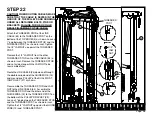
Page 24: ...r the V GROOVE PULLEY of the LEFT MID SWIVEL then up and around the two PULLEYS in the LEFT DOOR 8 as shown Route the MID PULLEY CABLE 51 around the two PULLEYS of the LEFT SIDE 3 then down through the GUIDE ROD SUPPORT 10 as shown Route the MID PULLEY CABLE 51 around the PULLEY of the HEAD PLATE PULLEY 24 then up through the GUIDE ROD SUPPORT 10 as shown Route the MID PULLEY CABLE 51 around the t...

Page 25: ...he BALL END of the MID PUL LEY CABLE 51 see inset following these steps Slide the HOUSING back onto the CABLE Pull down on the SPRING and insert the BALL END of the CABLE into the side of the CORE NOTICE MAKE SURE TO HOLD THE CABLE COUPLER VERTICAL TO PREVENT THE PINS FROM FALLING OUT DURING REASSEMBLY IF THE PINS FALL OUT ALIGN THE ANGLED SLOTS OF THE CORE WITH THE HORIZONTAL SLOT IN THE SLIDE AN...

Page 26: ...52 one of the FAST ATTACH CABLE COUPLERS must be removed from the end of the CABLE following the steps outlined in STEP 17 Route the BALL END of the UPPER PULLEY CABLE 52 around the V GROOVE PULLEY and 4 1 2 PULLEY on the LEFT SIDE of the TOP BOOM 4 then down toward the BASE 1 as shown Route the UPPER PULLEY CABLE 52 around the PULLEY of the PULLEY BRACKET 25 as shown 52 4 SPRING ROLLER PIN COUPLE...

Page 27: ...und the 4 1 2 PULLEY and V GROOVE PULLEY on the RIGHT SIDE of the TOP BOOM 4 as shown Reassemble the FAST ATTACH CABLE COUPLER to the BALL END of the UPPER PULLEY CABLE 52 following the steps out lined in STEP 19 4 52 SPRING ROLLER PIN COUPLER CORE SLIDE BOLT HOUSING ...

Page 28: ...inst the THREADED POST Remove the 1 2 JAM NUT from the other THREADED STUD on the LINK CABLE 53 a shown in inset Remove the THREADED STUD and set aside along with the JAM NUT to be reassembled later Route the LINK CABLE 53 down and through the double coiled end of the GUIDE WIRE 12 and around one PULLEY of the DUAL FLOAT ING PULLEY 27 as shown Reassemble the THREADED STUD and JAM NUT to the LINK C...

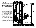
Page 29: ...ed in STEP 17 Attach the THREADED STUD of the LC LE CABLE 54 to the THREADED POST on the bottom of the FLOATING PULLEY BRACKET 25 as shown Leave a 1 gap between the THREADED STUD and the THREADED POST Tighten the 1 2 JAM NUT up against the THREADED POST as shown in inset Route the LC LE CABLE 54 around the FOURTH PULLEY of the BASE 1 then up to the DUAL FLOATING PULLEY 27 as shown Route the LC LE ...

Page 30: ...BASE 1 and route the LC LE CABLE 54 around the PULLEY of the CABLE TENSIONER and under the SECOND PULLEY of the BASE 1 as shown Route the LC LE CABLE 54 through the FRONT BASE TUBE and under the FIRST PULLEY of the BASE 1 as shown CABLE TENSIONER 1 54 FIRST PULLEY SECOND PULLEY 54 ...

Page 31: ...PULLEYS in the SEAT SUPPORT 17 as shown Route the LC LE CABLE 54 around the PUL LEY in the LC LE PIVOT 18 as shown Reassemble the FAST ATTACH CABLE COUPLER to the BALL END of the LC LE CABLE 54 following the steps outlined in STEP 19 BOLT SPRING ROLLER PIN COUPLER CORE SLIDE HOUSING 54 ...

Page 32: ... on the threaded ends of the cables Adjust the threaded ends in or out to make the cable tighter or looser at any or all of the adjust ment points as shown NOTICE TIGHTEN ALL JAM NUTS CON NECTIONS WHEN FINISHED ADJUSTING SECURELY assemble the two BASE SHOUDS 28 to the BASE 1 using Six 1 4 X 1 2 BOLTS 49 Six 1 4 WASHERS 50 CABLE ADJUST POINT CABLE ADJUST POINT 1 28 50 1 4 X 1 2 49 ...

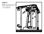
Page 33: ...Page 33 1 2 3 4 5 6 STEP 27 SECURELY assemble the BADGE PLATE 29 to the LEFT and RIGHT SIDES 3 2 using Two 1 4 X 1 2 BOLTS 49 Two 1 4 WASHERS 50 49 1 4 X 1 2 29 3 2 50 ...

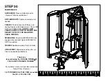
Page 34: ... 1 4 WASHERS 50 SECURELY assemble the LEFT DOOR SHROUD WITH STAND OFF 31 to the LEFT DOOR 8 using Eight 1 4 X 1 2 BOLTS 49 Eight 1 4 WASHERS 50 Remove the backing from the F3 PLACARD 44 and attach it to the STAND OFF on the LEFT DOOR 8 as shown Page 34 1 2 3 4 5 6 STEP 28 1 4 X 1 2 49 50 6 30 8 31 44 F3 PLACARD ...

Page 35: ...icks To remove theACCESSORY push SLIDE END of the CABLE COUPLER and pull the ACCES SORY out To use the ANKLE STRAP 65 attach one end of the ANKLE STRAP 65 to the UNIVERSAL ADAPTER 63 using a SNAP HOOK 64 then wrap ANKLE STRAP 65 around ankle and attach the other end to the SNAP HOOK 64 Insert the STRAP HANDLE END into the CABLE COUPLER until it clicks Page 35 1 2 3 4 5 6 STEP 29 58 56 64 63 CABLE ...

Page 36: ...P 27 FOR ADJUSTING CABLE TENSION SPRING PINS Check that SPRING PINS fully engage when released Tighten SPRING PIN NUTS as needed FRAME Wipe down and dry Polish and wax UPHOLSTERY Wipe down and dry after use Clean and condition periodically Thank you for purchasing the TORQUE FITNESS F3 FOLD AWAY STRENGTH TRAINERTM TM TM TM TM For customer service call your local authorized Torque Fitness Dealer or...

Page 37: ...Page 37 ...

Page 38: ...2 Where the threaded end of the Link Cable 53 attaches to the Pulley Bracket 26 step 22 3 Where the threaded end of the LC LE Cable 54 attaches to the Floating Pulley Bracket 25 step 23 4 The threaded pulley bracket that is attached to the top of the weight stack selector stem step 18 _______ Ensure all adjustments are smooth and easy and that all pull pins easily engage and disengage in all of th...

Page 39: ...Page 39 ...

Page 40: ...13750 Crosstown Drive NW Suite 204 Andover MN 55304 USA 7 WARRANTYDISCLAIMER OUR SOLEAND EXCLUSIVE WARRANTY TO YOU WITH RESPECT TOYOUR PURCHASED PRODUCT IS THE LIMITED WARRANTYSET FORTHABOVE UNLESS OTHERWISE SPECIFICALLY PROVIDED ABOVE WE MAKE NO REPRESENTATIONS OR WARRANTIES REGARDING THE PRODUCT AND WE HEREBY SPECIFICALLY EXCLUDE AND DISCLAIM ANYANDALL WARRANTIES WITH RESPECT TO THE PRODUCT INCL...

Page 41: ... by You conforms to such sample or model 12 NON ASSIGNABILITY In no event is any affirmation representation or warranty relating to the Product applicable to anyone other than You and no other person is entitled to rely thereon Your rights with respect to the LIMITED WARRANTY may not be assigned or transferred to any third party and any attempted such assignment or transfer shall be null and void ...

Page 42: ...Page 42 ...
Page 43: ...PLACE STAMP HERE Torque Fitness 13750 Crosstown Drive NW Suite 204 Andover MN 55304 USA FOLD HERE ...

Page 44: ... _ _ _ Apt Suite _ _ _ _ City _ _ _ _ _ _ _ _ _ _ _ _ _ _ _ _ _ _ _ _ _ _ _ _ _ _ _ _ State _ _Zip code _ _ _ _ _ _ _ _ _ Area Code _ _ _ Telephone _ _ _ _ _ _ _ Your Email Address _ _ _ _ _ _ _ _ _ _ _ _ _ _ _ _ _ _ _ _ _ _ To allow us to serve you better please take a few moments to complete and return your warranty registration YOU MAY ALSO REGISTER ONLINE AT www torquefitness com For further i...

Reviews: