background image

Operation

22

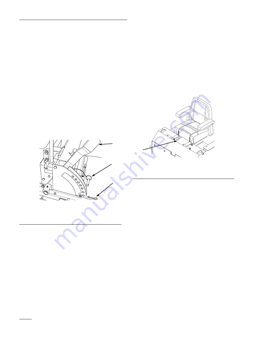
Adjusting Height-of-Cut

The height-of-cut is adjusted from 1-1/2” to 5”
(38 to 127 mm) in 1/2” (13 mm) increments by
relocating clevis pin in different hole locations.

1.

Raise the height-of-cut lever to the transport
position (also the 5” (127 mm) cutting height
position) (Fig. 11).

2.

To adjust, remove hairpin cotter and clevis pin
from height-of-cut bracket (Fig. 11).

3.

Select hole in height-of-cut bracket
corresponding to the height-of-cut desired. Lift
handle to transport position, insert clevis pin
(Fig. 11).

4.

Secure clevis pin with hairpin cotter (Fig. 11).

1

m-3654

3

2

Figure 11

1.

Height of cut lever

2.

Clevis Pin

3.

Hairpin Cotter

Positioning the Seat

The seat can move forward and backward. Position
the seat where you have the best control of the
machine and are most comfortable.

1.

To adjust, move the lever sideways to unlock
seat (Fig. 12).

2.

Slide the seat to the desired position and release
lever to lock in position.

1

1200

m–3655

Figure 12

1.

Adjustment knob

Summary of Contents for z-252

Page 1: ...arefully It contains information about your safety and the safety of others Also become familiar with the controls and their proper use before you operate the product FORM NO 3319 816 Z Master 250 Ser...

Page 2: ...products you are responsible for using the product properly and safely You are also responsible for training persons who you allow to use the product about safe operation The warning system in this m...

Page 3: ...ntrols 16 Parking Brake 16 Starting and Stoppingv the Engine 17 Operating the Power Take Off PTO 18 The Safety Interlock System 19 Driving Forward or Backward 20 Page Stopping the Machine 20 Instrumen...

Page 4: ...ed grass covered land without an approved spark arrester muffler is a violation of the law Other states may have similar laws General Operation 1 Read understand and follow all instructions in the ope...

Page 5: ...n the slope Follow the manufacturer s recommendations for wheel weight or counterweights to improve stability Use extra care with grass catchers or other attachments These can change the stability of...

Page 6: ...ever run a machine inside a closed area 4 Keep nuts and bolts tight especially the blade attachment bolts Keep equipment in good condition 5 Never tamper with safety devices Check safety systems for p...

Page 7: ...Safety 5 Slope Chart Read all safety instructions on pages 2 4...

Page 8: ...6...

Page 9: ...RVOIR Part No E513890 ON RIGHT SIDE OF HEIGHT OF CUT PLATE Part No E633345 TOP OF CONSOLE UNDER SEAT Part No E513747 ON TOP OF CONSOLE LEFT AND RIGHT SIDES Part No E633354 ON RUBBER FLAP BEHIND SEAT P...

Page 10: ...TREST Part No E633766 ON RUBBER FLAP BEHIND SEAT Part No E513748 ON CONTROL PANEL Part No E633738 ON TOP OF RIGHT ENGINE BAFFLE Part No E633771 E ONHYDRAULIC TANK Part No 65 2690 ON LEFT FRONT OF FRAM...

Page 11: ...an open flame or where gasoline fumes may be ignited by a spark Store gasoline in an approved container and keep it out of the reach of children Never buy more than a 30 day supply of gasoline Stabil...

Page 12: ...tall motion control levers Strut right Strut left Bolt 5 8 11 x 5 127 mm Lock washer 5 8 Nut 5 8 11 Bolt 7 16 14 x 1 1 2 38 mm Flange nut 7 16 14 Chain assembly 1 1 2 2 2 4 8 4 Install mower mounts to...

Page 13: ...ghten until snug then loosen so the rod pivots freely 3 1 m 3750 2 Figure 1 1 L end of retaining rod 2 Locknut 5 16 3 Bolt 5 16 18 x 1 26 mm Tire Pressure Check the air pressure in the front and rear...

Page 14: ...ounting plate and tighten until snug 12 Align the front rear position of the levers with each other in the neutral position Loosen hardware and adjustment by sliding tilting the lever s forward or bac...

Page 15: ...h skin eyes or clothing Wear safety glasses to shield your eyes and rubber gloves to protect your hands Fill the battery where clean water is always available for flushing the skin Follow all instruct...

Page 16: ...osition battery in tray with terminal posts toward the engine Fig 7 7 Slide the red terminal boot onto the positive red battery cable 8 Install the positive red battery cable to positive battery termi...

Page 17: ...mention 3 Remove one 7 16 14 flange nut from bolt in each chain assembly Fig 9 4 Place bolt of chain into traction unit lift arm slot and secure with previously removed 7 16 14 flange nut Fig 9 Tighte...

Page 18: ...uel shut off valve Parking Brake Always set the parking brake when you stop the machine or leave it unattended IMPORTANT Do not park on slopes unless wheels are chicked or blocked Setting the Parking...

Page 19: ...fore starting a cold engine 6 Turn ignition key START to energize starter When engines starts release key IMPORTANT Do not engage starter for more than 10 seconds at a time If engine fails to start al...

Page 20: ...e 5 Close fuel shut off valve on front panel before transporting or storing machine IMPORTANT Make sure fuel shut off valve is closed before transporting or storing machine as fuel leakage may occur O...

Page 21: ...ow have an Authorized Service Dealer repair the safety system immediately 1 Sitting on the seat ENGAGE parking brake and move PTO ON Try starting the engine the engine should not crank 2 Sitting on th...

Page 22: ...1 Motion control lever neutral lock position 2 Center un lock position 3 Forward 4 Backward Backward 1 Move levers to the center un locked position 2 To go backward slowly pull the motion control lev...

Page 23: ...es Each tank connects to the fuel shut off valve in the control panel from there a common fuel line leads to the engine Fig 10 To use the right side fuel tank rotate the fuel shut off valve 1 4 turn t...

Page 24: ...in height of cut bracket corresponding to the height of cut desired Lift handle to transport position insert clevis pin Fig 11 4 Secure clevis pin with hairpin cotter Fig 11 1 m 3654 3 2 Figure 11 1 H...

Page 25: ...engine 2 Rotate the by pass valves counterclockwise 1 turn to push This allows hydraulic fluid to by pass the pump enabling the wheels to turn Fig 13 IMPORTANT Rotate by pass valve a maximum of 2 tur...

Page 26: ...r wear cracks X X Gasoline drain X Cooling systems clean X X X Hydraulic lines check X X Battery check electrolyte X X Battery charge Disconnect cables X Fuel Filter replace X X Tires check pressure X...

Page 27: ...ove the air cleaner cover Fig 14 1 2 m 3214 3 4 6 8 7 5 Figure 14 1 Knob 2 Air cleaner cover 3 Cover nut 4 Cover 5 Foam element 6 Paper element 7 Rubber seal 8 Air cleaner base 3 Carefully slide the f...

Page 28: ...t engine damage always operate the engine with the complete foam and paper air cleaner assembly installed 1 Carefully slide the foam element onto the paper air cleaner element Fig 14 2 Place the air c...

Page 29: ...3217 m 3219 Figure 17 1 Oil dipstick 2 Filler tube 3 Metal end Changing Draining Oil 1 Start the engine and let it run five minutes This warms the oil so it drains better 2 Park the machine so that t...

Page 30: ...contacts the filter adapter then tighten the filter an additional 1 2 turn Fig 19 6 Fill the crankcase with the proper type of new oil refer to Changing Draining Oil page 27 Spark Plug Check the spark...

Page 31: ...the spark plug s Make sure the air gap is set correctly 2 Tighten the spark plug s to 20 ft lb 27 N m 3 Push the wire s onto the spark plug s Fig 20 Greasing and Lubrication Lubricate the machine when...

Page 32: ...em after every 50 operating hours or monthly whichever occurs first Fig 24 Check the tires when they are cold to get the most accurate pressure reading Pressure 13 psi 90 kPa drive wheels and castor w...

Page 33: ...evel surface to assure fuel tank drains completely Then disengage the power take off PTO set the parking brake and turn the ignition key to OFF to stop the engine Remove the key 2 Close fuel shut off...

Page 34: ...2 Baffle 3 Fluid level Full POTENTIAL HAZARD Hydraulic fluid escaping under pressure can penetrate skin and cause injury WHAT CAN HAPPEN Fluid accidentally injected into the skin must be surgically r...

Page 35: ...engine and let run for about two minutes to purge air from the system Stop the engine and check for leaks If one or both wheels will not drive refer Bleeding Hydraulic System page 33 10 Check fluid l...

Page 36: ...ach lever spring and rod separately 1 Stop engine remove ignition key and tilt seat forward 2 Begin with either the left or right motion control lever Move lever to the neutral position and pull lever...

Page 37: ...el is still or slightly creeps in reverse Fig 30 13 Move motion control lever forward and reverse then back to neutral Wheel must stop turning or slightly creep in reverse Note Motion control lever mu...

Page 38: ...e trunnion roller and the collar on brake rod Measurement should be 3 16 1 4 5 7 mm Fig 32 7 If adjustment is necessary loosen the jam nut directly below the yoke Turn the bottom rod until the correct...

Page 39: ...hly with the electrolyte solution 1 Clean the top of the battery with a paper towel 2 Lift off the filler caps Fig 34 3 Slowly pour distilled water into each battery cell until the level is up to the...

Page 40: ...Maintenance 38 Wiring Diagram...

Page 41: ...gine oil into the spark plug hole Now use the starter to crank the engine and distribute the oil inside the cylinder Install the spark plug s Do not install the wire on the spark plug s 8 Check the ti...

Page 42: ...or replace air cleaner element 5 Spark plug wires is loose or disconnected 5 Install wires on spark plug 6 Spark plugs are pitted fouled or gap is incorrect 6 Install new correctly gapped spark plugs...

Page 43: ...ooling fins and air passages Abnormal vibration 1 Engine mounting bolts are loose 1 Tighten engine mounting bolts 2 Loose engine pulley idler pulley or blade pulley 2 Tighten the appropriate pulley 3...

Page 44: ...eep The Warranty In Effect You must maintain your TORO Product by following the main tenance procedures described in the operator s manual Such routine maintenance whether performed by a dealer or by...

Reviews: