


Maintenance
26
Battery
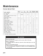
Service Interval/Specification
Check the electrolyte level in the battery after every 5
operating hours. Always keep the battery clean and
fully charged. Use a paper towel to clean the battery
and battery box. If the battery terminals are corroded,
clean them with a solution of four parts water and one
part baking soda. Apply a light coating of grease to
the battery terminals to prevent corrosion.
Voltage: 12 v, 160 Cold Cranking Amps
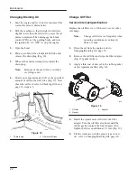
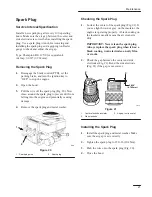
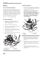
Removing the Battery
1.
Disengage the blade control (PTO), set the
parking brake, and turn the ignition key to
“OFF” to stop the engine.
2.
Tip the seat forward to see the battery.
3.
Disconnect the negative (black) ground cable
from the battery post (Fig. 29).
4.
Slide the rubber cover up the positive (red)
cable. Disconnect the positive (red) cable from
the battery post (Fig. 29).
5.
Remove the battery box, battery, and long vent
tube from the chassis (Fig. 30).
1
2
3
4
5
1876
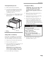
Figure 29
1. Negative cable (black)
2. Rubber cover
3. Positive cable (red)
4. Battery box
5. Bolt and wing nut
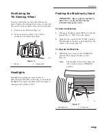
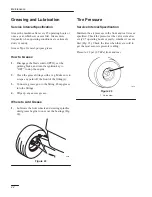
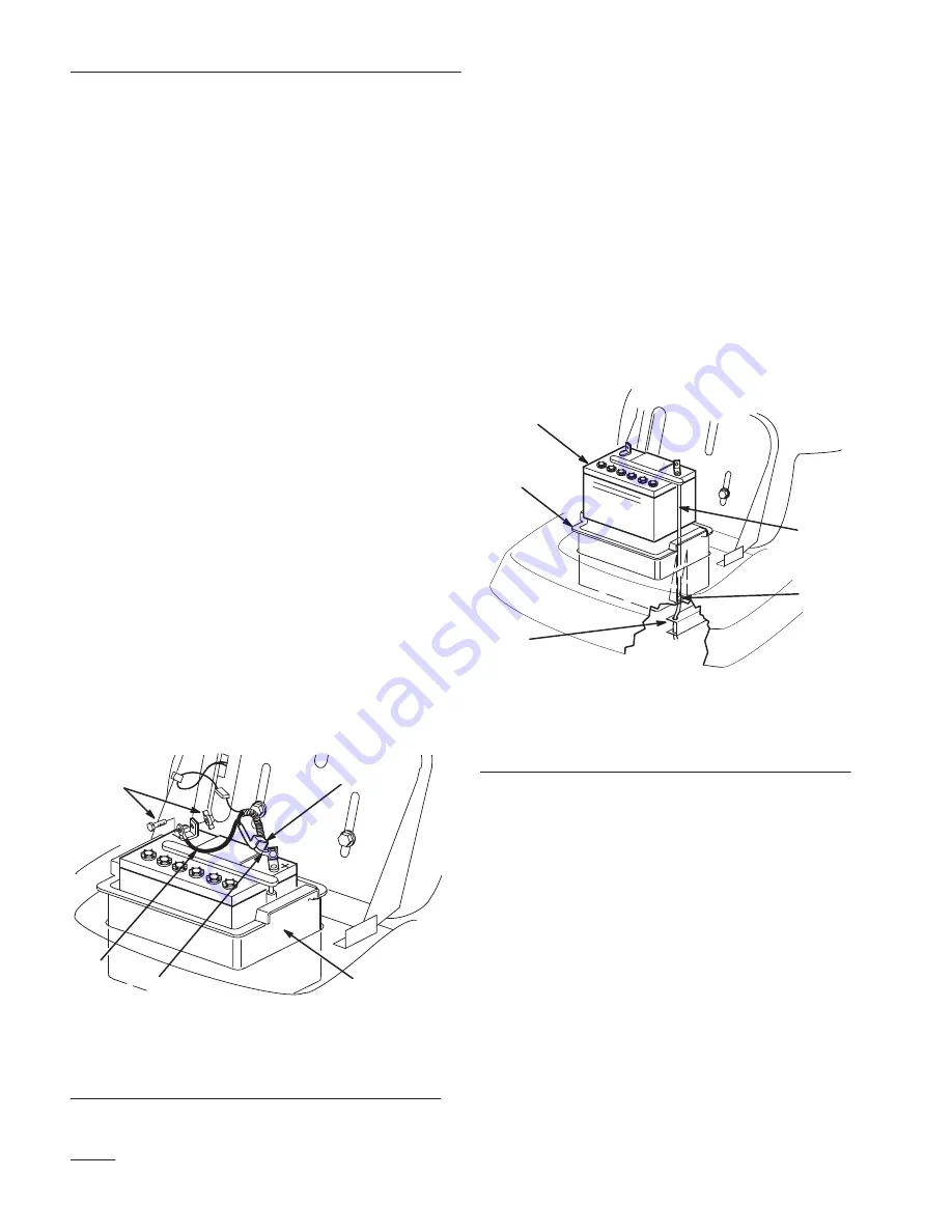
Installing the Battery
1.
Put the battery into the battery box and slide the
vent tube into the channel and through the slot in
the bottom of the box (Fig. 30).
IMPORTANT: Look down into the cut out
area where the battery box fits into the
chassis. Notice the holes at the end of the right
frame member (Fig. 30). Always install the
long battery vent tube through the holes to
prevent battery acid from corroding the
tractor and mower.
1
2
3
4
5
2347
Figure 30
1. Battery
2. Battery box
3. Vent tube
4. Slot in battery box
5. Hole in frame
2.
Install the battery box and battery into the
chassis (Fig. 30). Make sure to slide the end of
the vent tube through the hole in the frame
(Fig. 30).
3.
Using the bolt and wing nut, connect the positive
(red) cable to the positive (+) battery post
(Fig. 29). Slide the rubber cover over the battery
post.
4.
Using the bolt and wing nut, connect the
negative (black) cable to the negative (–) battery
post (Fig. 29).
Summary of Contents for Wheel Horse 16-44 HXLE
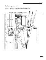
Page 7: ...Safety 5 Slope Chart Read all safety instructions on pages 2 8...
Page 34: ......
Page 75: ......
Page 76: ......
Page 77: ......
Page 78: ......
Page 79: ......
Page 80: ......
Page 81: ......
Page 82: ......
Page 83: ......
Page 84: ......
Page 85: ......
Page 86: ......
Page 87: ......
Page 88: ......
Page 89: ......
Page 90: ......
Page 91: ......
Page 92: ......
Page 93: ......
Page 94: ......
Page 95: ......
Page 96: ......
Page 97: ......
Page 98: ......
Page 99: ......
Page 100: ......
Page 101: ......
Page 102: ......
Page 103: ......
Page 104: ......
Page 105: ......
Page 106: ......
Page 107: ......
Page 108: ......


