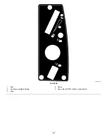

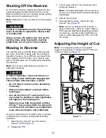
g019929
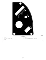
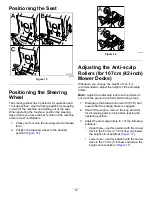
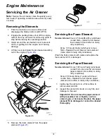
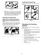
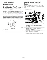
Figure 17
1.
Anti-scalp roller
4.
Upper hole—the mower
deck in the 63mm (2-1/2
inches) and below the
height-of-cut positions
2.
Lower hole—the mower
deck in the 76mm (3
inches) and above the
height-of-cut positions
5.
Bolt
3.
Flange nut
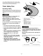
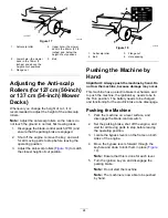
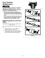
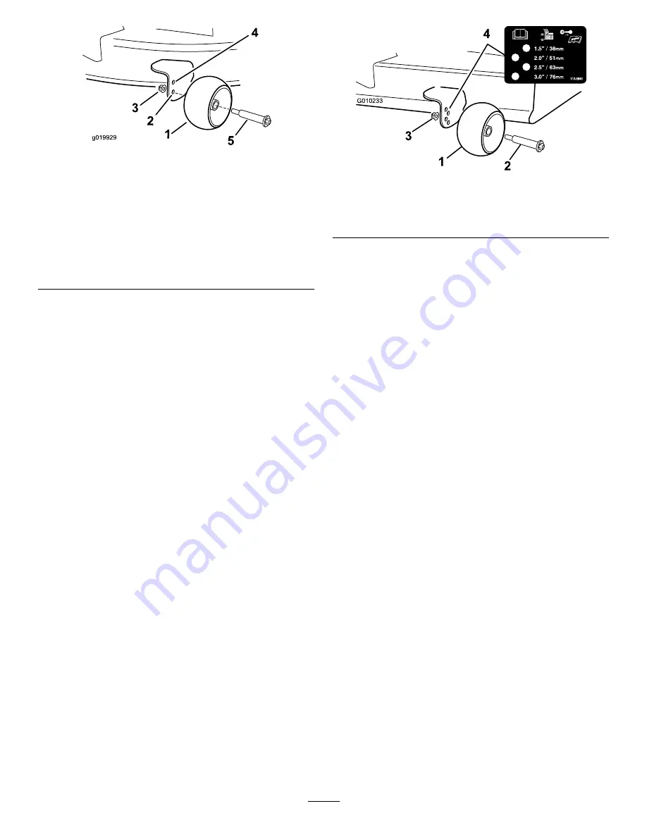
Adjusting the Anti-scalp
Rollers (for 127 cm (50-inch)
or 137 cm (54-inch) Mower
Decks)
Whenever you change the height of cut, it is
recommended to adjust the height of the anti-scalp
rollers.
Note:
Adjust the anti-scalp rollers so the rollers do
not touch the ground in normal, flat mowing areas.
1.
Disengage the blade-control switch (PTO) and
ensure that the parking brake is engaged.
2.
Shut off the engine, remove the key, and wait
for all moving parts to stop before leaving the
operating position.
3.
Adjust the anti-scalp rollers (
) to match
the closest height-of-cut position.
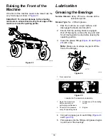
g010233
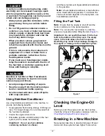
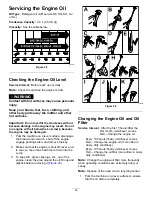
Figure 18
1.
Anti-scalp roller
3.
Flange nut
2.
Bolt
4.
Hole spacing
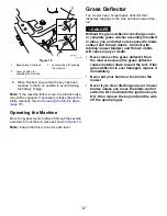
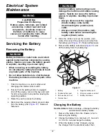
Pushing the Machine by
Hand
Important:
Always push the machine by hand. Do
not tow the machine, because damage may occur.
This machine has an electric-brake mechanism, and
to push the machine, the ignition key needs to be in
the R
UN
position. The battery needs to be charged
and functioning for the electric brake to be disengage.
Pushing the Machine
1.
Park the machine on a level surface, and
disengage the blade-control switch.
2.
Set the parking brake, shut off the engine, and
wait for all moving parts to stop before leaving
the operating position.
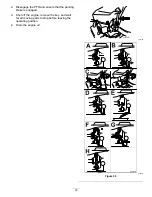
3.
Locate the bypass levers on the frame on both
sides of the engine.
4.
Move the bypass levers forward through the
keyhole and down to lock them in place (
Note:
Ensure that this is done for each lever.
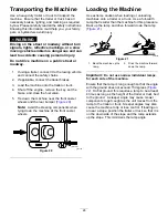
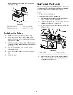
5.
Turn the ignition key on and disengage the
parking brake.
Note:
Do not start the machine.
Note:
The machine is now able to be pushed
by hand.
24
Summary of Contents for TimeCutter SW 5000
Page 52: ...Schematics g027754 Electrical Diagram Rev A 52 ...
Page 53: ...Notes ...
Page 54: ...Notes ...
Page 55: ...Notes ...


