background image

Pre-Maintenance
Procedures

Maintenance and Storage
Safety

Before repairing the machine do the following:

Disengage the drives.

Engage the parking brake.

Shut off the engine and remove the key.

Disconnect the spark-plug wire.

Park the machine on a level surface.

Clean grass and debris from the cutting unit, drives,
mufflers, and engine to help prevent fires.

Clean up oil or fuel spills.

Let the engine cool before storing the machine.

Do not store the machine or fuel near flames or drain
the fuel indoors.

Do not allow untrained personnel to service the machine.

Use jack stands to support the machine and/or
components when required.

Carefully release pressure from components with stored
energy.

Disconnect the battery or remove the spark-plug wire
before making any repairs. Disconnect the negative
terminal first and the positive terminal last. Connect the
positive terminal first and negative last.

Use care when checking the blades. Wrap the blade(s)
or wear thickly padded gloves, and use caution when
servicing them. Only replace blades; do not straighten
or weld them.

Keep your hands and feet away from moving parts.
If possible, do not make adjustments with the engine
running.

Keep all parts in good working condition and all hardware
tightened, especially the blade-attachment bolts. Replace
all worn or damaged decals.

Never interfere with the intended function of a safety
device or reduce the protection provided by a safety
device. Check their proper operation regularly.

To ensure optimum performance and continued safety
certification of the machine, use only genuine Toro
replacement parts and accessories. Replacement parts
and accessories made by other manufacturers could be
dangerous, and such use could void the product warranty.

Check the parking brake operation frequently. Adjust and
service as required.

Releasing the Mower-Deck
Curtain

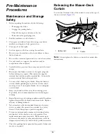
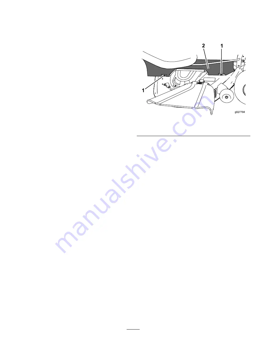
Loosen the 2 bottom bolts of the curtain to access the top of
the mower deck (

Figure 42

).

g027794

Figure 42

1.

Bottom bolt

2.

Curtain

Note:

Always tighten the bolts to connect the curtain after

maintenance.

33


Summary of Contents for TimeCutter HD X5450

Page 1: ...No 3410 275 Rev B TimeCutter HD XS4850 and X5450 Riding Mower Model No 74866 Serial No 400000000 and Up Model No 74867 Serial No 400000000 and Up Register at www Toro com Original Instructions EN 3410 275 B ...

Page 2: ...cultural uses Read this information carefully to learn how to operate and maintain your product properly and to avoid injury and product damage You are responsible for operating the product properly and safely You may contact Toro directly at www Toro com for product safety and operation training materials accessory information help finding a dealer or to register your product Whenever you need se...

Page 3: ...ion Safety 29 Pushing the Machine by Hand 30 Transporting the Machine 30 Loading the Machine 31 Maintenance 32 Recommended Maintenance Schedule s 32 Pre Maintenance Procedures 33 Maintenance and Storage Safety 33 Releasing the Mower Deck Curtain 33 Engine Maintenance 34 Engine Safety 34 Servicing the Air Cleaner 34 Servicing the Engine Oil 35 Servicing the Spark Plug 37 Cleaning the Cooling System...

Page 4: ...achine without all guards and other safety protective devices in place and working on the machine Keep clear of any discharge opening Keep bystanders a safe distance away from the machine Keep children out of the operating area Never allow children to operate the machine Stop the machine and shut off the engine before servicing fueling or unclogging the machine Improperly using or maintaining this...

Page 5: ...s 15 degrees Use the slope chart to determine the degree of slope of hills before operating Do not operate this machine on a slope greater than 15 degrees Fold along the appropriate line to match the recommended slope 2 Align this edge with a vertical surface a tree building fence pole etc 3 Example of how to compare slope with folded edge 5 ...

Page 6: ... decalbatterysymbols Battery Symbols Some or all of these symbols are on your battery 1 Explosion hazard 6 Keep bystanders a safe distance away from the battery 2 No fire open flame or smoking 7 Wear eye protection explosive gases can cause blindness and other injuries 3 Caustic liquid chemical burn hazard 8 Battery acid can cause blindness or severe burns 4 Wear eye protection 9 Flush eyes immedi...

Page 7: ...th an open deck use a bagger or a baffle 4 Entanglement hazard keep away from moving parts keep all guards and shields in place decal130 0765 130 0765 1 Read the Operator s Manual 3 Remove the key from the ignition and read the Operator s Manual before performing maintenance 2 Height of cut selection decal130 0654 130 0654 1 Transport lock 3 Height of cut 2 Transport unlock decal131 1097 131 1097 ...

Page 8: ... key and disconnect the spark plug wire 6 Crushing dismemberment hazard of bystanders in reverse and forward do not carry passengers look behind and down when reversing 3 Cutting dismemberment hazard mower blade entanglement hazard belt stay away from moving parts and keep all guards and shields in place 7 Tipping hazard do not use the machine near drop offs with slopes greater than 15 degrees or ...

Page 9: ...e 2 Slow 5 PTO engage 3 Choke decal136 4243 136 4243 1 Fast 4 Reverse 2 Slow 5 Parking brake disengaged 3 Neutral 6 Parking brake engaged decal136 4244 136 4244 1 Fast 3 Neutral 2 Slow 4 Reverse decal136 4245 136 4245 1 Slow 3 Fast 2 Transport 9 ...

Page 10: ...hours 4 Check the tire pressure every 25 operating hours 2 Engine oil 5 Read the Operator s Manual before performing maintenance 3 Check the tire pressure every 25 operating hours decal136 9186 136 9186 1 Read the Operator s Manual before adding weight to the bucket 10 ...

Page 11: ...come familiar with all controls in Figure 5 and Figure 6 before you start the engine and operate the machine g188738 Figure 5 1 Hour meter 4 Ignition switch 2 Throttle control 5 PTO switch 3 Choke control 6 12 V power point g188776 Figure 6 1 Fuel gauge Fuel Gauge The fuel gauge displays the amount of fuel in the tank Figure 6 Throttle Control The throttle controls the engine speed and it has a co...

Page 12: ...t down Foot Pedal Deck Lift System The foot pedal deck lift system allows you to lower and raise the deck from the seated position You can use the foot pedal to lift the deck briefly to avoid obstacles or lock the deck in the highest height of cut or transport position Figure 4 Smart Speed Control System Lever The Smart Speed Control System lever located below the operating position gives you a ch...

Page 13: ...uel dispenser nozzle Do not operate the machine without the entire exhaust system in place and in proper working condition Keep the fuel dispenser nozzle in contact with the rim of the fuel tank or container opening at all times until fueling is complete Do not use a nozzle lock open device If you spill fuel on your clothing change your clothing immediately Wipe up any fuel that spills Never overf...

Page 14: ...gines take time to develop full power Mower decks and drive systems have higher friction when new placing additional load on the engine Allow 40 to 50 hours of break in time for new machines to develop full power and best performance Think Safety First Please read all safety instructions and symbols in the safety section Knowing this information could help you or bystanders avoid injury DANGER Ope...

Page 15: ... safety system immediately 1 Sit on the seat engage the parking brake and move the blade control switch PTO to the ON position Try starting the engine the engine should not crank 2 Sit on the seat engage the parking brake and move the blade control switch PTO to the OFF position Move either motion control lever out of the NEUTRAL LOCK position Try starting the engine the engine should not crank Re...

Page 16: ...e slots for the rear shock assemblies have detent positions for reference You can position the rear shock assemblies anywhere in the slot not just in the detent positions The following graphic shows the position for a soft or firm ride and the different detent positions Figure 11 g195744 Figure 11 1 Firmest position 3 Detents in the slots 2 Softest position Note Ensure that the left and right rear...

Page 17: ...chine to slide Ensure that all drives are in neutral the parking brake is engaged and you are in the operating position before you start the engine Keep your hands and feet away from the cutting units Keep clear of the discharge opening at all times Look behind and down before backing up to be sure of a clear path Use care when approaching blind corners shrubs trees or other objects that may obscu...

Page 18: ...vailable for the machine as an accessory A ROPS is recommended if you will be mowing next to drop offs near water or on steep banks which could result in a rollover Contact an Authorized Service Dealer for more details Operating the Parking Brake Always engage the parking brake when you stop the machine or leave it unattended Engaging the Parking Brake WARNING The parking brake may not hold the ma...

Page 19: ...erating the Throttle You can move the throttle control between the FAST and SLOW positions Figure 19 Always use the FAST position when turning on the mower deck with the blade control switch PTO g187517 Figure 19 Operating the Choke Use the choke to start a cold engine 1 If the engine is cold use the choke to start the engine 2 Pull up on the choke knob to engage the choke before using the ignitio...

Page 20: ...letely STA RT RU N STO P G008947 g008947 Figure 21 2 Turn the ignition key to shut off the engine Starting and Shutting Off the Engine Starting the Engine Note A warm or hot engine may not require choking Important Do not engage the starter for more than 5 seconds at a time Engaging the starter motor for more than 5 seconds can damage the starter motor If the engine fails to start wait 10 seconds ...

Page 21: ...ons per minute Place the throttle control in the FAST position for best performance Always operate in the full throttle position when mowing CAUTION The machine can spin very rapidly which may cause you to lose control of machine resulting in personal injury or damage to machine Use caution when making turns Slow the machine down before making sharp turns Driving Forward Note The engine stops when...

Page 22: ...ining X Bagging X Mulching X Normal mowing X Transport X Trim This is the lowest speed The suggested uses for this speed are as follows Parking Heavy wet grass mowing conditions Training Tow This is the medium speed The suggested uses for this speed are as follows Bagging Mulching Mow This is the fastest speed The suggested uses for this speed are as follows Normal mowing Transporting the machine ...

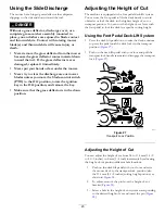
Page 23: ...e foot pedal to lift the deck briefly to avoid obstacles or lock the deck in the highest height of cut or transport position You can use the height of cut lever with the foot pedal to lock the deck in a specific cutting height Using the Foot Pedal Deck Lift System Press the deck lift pedal down to raise the deck continue to press the pedal until the deck locks in the transport position Figure 27 P...

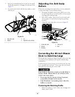
Page 24: ...ust the anti scalp rollers as shown in Figure 29 g029955 g029955 Figure 29 1 Anti scalp roller 4 Flange nut 2 Spacer 5 Bolt 3 Bushing Converting the 48 inch Mower Deck to Side Discharge The mower deck and mower blades shipped with the machine were designed for optimum mulching and side discharge performance Install the fasteners into the same holes in the deck that they were originally removed fro...

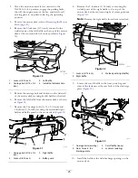
Page 25: ...wer deck as shown in Figure 30 7 Remove the 2 carriage bolts 5 16 x 3 4 inch and 2 locknuts 5 16 inch securing the assembled right baffle and baffle guard to the mower deck Figure 31 g191136 Figure 31 1 Carriage bolt 5 16 x 3 4 inch 3 Right baffle 2 Locknut 5 16 inch 4 Baffle guard 8 Remove the 2 locknuts 5 16 inch to securing the welded posts of the right baffle to the top of the mower deck at th...

Page 26: ...ower Deck page 47 4 Remove the 3 locknuts 5 16 inch secured to the welded posts of the left baffle on the top of the mower deck at the center left of center and left positions Figure 34 G011149 1 1 2 3 4 g011149 Figure 34 1 Locknut 5 16 inch 3 Left baffle 2 Carriage bolt 5 16 x 3 4 inch 4 Install the fasteners here 5 Remove the carriage bolt and locknut on the side wall of the mower deck securing ...

Page 27: ...e the 2 locknuts 5 16 inch securing the welded posts of the right baffle to the top of the mower deck at center and right of center positions Figure 36 G010704 1 2 3 g010704 Figure 36 1 Locknut 5 16 inch 3 Welded posts right baffle 2 Right baffle 12 Remove the carriage bolt and locknut securing the right baffle to the top of the mower deck and remove the right baffle from the mower deck Figure 36 ...

Page 28: ...round However the cutting height used in the past is generally the best one to use When cutting grass longer than 15 cm 6 inches tall you may want to cut the lawn twice to ensure an acceptable quality of cut Cutting a Third of the Grass Blade It is best to cut only about a third of the grass blade Cutting more than that is not recommended unless grass is sparse or it is late fall when grass grows ...

Page 29: ...d or worn replace it immediately with a genuine Toro replacement blade After Operation After Operation Safety General Safety Clean grass and debris from the cutting units mufflers and engine compartment to help prevent fires Clean up oil or fuel spills Shut off the fuel before storing or transporting the machine Disengage the drive to the attachment whenever you are transporting or not using the m...

Page 30: ...wn to lock them in place as shown in Figure 38 Note Do this for each lever Transporting the Machine Use a heavy duty trailer or truck to transport the machine Ensure that the trailer or truck has all necessary brakes lighting and marking as required by law Please carefully read all the safety instructions Knowing this information could help you your family pets or bystanders avoid injury WARNING D...

Page 31: ...use individual ramps for each side of the machine Do not exceed a 15 degree angle between the ramp and the ground or between the ramp and the trailer or truck Ensure that the length of ramp is at least 4 times as long as the height of the trailer or truck bed to the ground This ensures that the ramp angle does not exceed 15 degrees on flat ground Back up ramps and drive forward down ramps Avoid su...

Page 32: ...Every 100 hours Replace the air cleaner foam element more often in dusty dirty conditions Service the air cleaner paper element more often in dusty dirty conditions Change the engine oil more often in dusty dirty conditions Change the oil filter more often in dusty dirty conditions Check the spark plug s Check the in line fuel filter Every 200 hours Replace the air cleaner paper element more often...

Page 33: ...blades Wrap the blade s or wear thickly padded gloves and use caution when servicing them Only replace blades do not straighten or weld them Keep your hands and feet away from moving parts If possible do not make adjustments with the engine running Keep all parts in good working condition and all hardware tightened especially the blade attachment bolts Replace all worn or damaged decals Never inte...

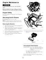
Page 34: ...ut off the engine remove the key and wait for all moving parts to stop before leaving the operating position 3 Clean around the air cleaner cover to prevent dirt from getting into the engine and causing damage 4 Lift the cover and rotate the air cleaner assembly out of the engine Figure 43 g027800 g027800 g027801 g027801 Figure 43 5 Remove the foam element from the paper element Figure 44 g027802 ...

Page 35: ...E 5W 30 10W 30 SAE 30 SYNTHETIC 5W 20 5W 30 10W 30 g029683 g029683 Figure 45 Checking the Engine Oil Level Service Interval Before each use or daily Note Check the oil when the engine is cold WARNING Contact with hot surfaces may cause personal injury Keep your hands feet face clothing and other body parts away the muffler and other hot surfaces Important If you overfill or underfill the engine cr...

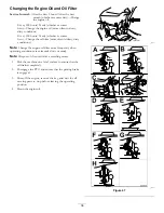
Page 36: ...ten in dusty dirty conditions Note Change the engine oil filter more frequently when operating conditions are extremely dusty or sandy Note Dispose of the used oil at a recycling center 1 Park the machine on a level surface to ensure that the oil drains completely 2 Disengage the PTO and ensure that the parking brake is engaged 3 Shut off the engine remove the key and wait for all moving parts to ...

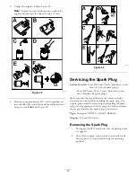
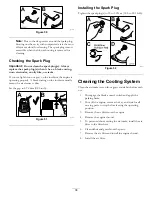
Page 37: ... the spark plug s Every 200 hours Every 2 years whichever comes first Replace the spark plug s Make sure that the air gap between the center and side electrodes is correct before installing the spark plug Use a spark plug wrench for removing and installing the spark plug s and a gapping tool feeler gauge to check and adjust the air gap Install a new spark plug s if necessary Type Champion RN9YC or...

Page 38: ...irty Set the gap to 0 76 mm 0 03 inch B A g027479 g027479 Figure 51 Installing the Spark Plug Tighten the spark plug s to 25 to 30 N m 18 5 to 22 1 ft lb B A 25 30 N m 18 5 22 1 ft lb g027960 C D g027960 Figure 52 Cleaning the Cooling System Clean the air intake screen from grass and debris before each use 1 Disengage the blade control switch and apply the parking brake 2 Shut off the engine remov...

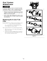
Page 39: ...re a spark may ignite the fuel fumes Replacing the In Line Fuel Filter Service Interval Every 100 hours Yearly whichever comes first Check the in line fuel filter Every 200 hours Every 2 years whichever comes first Replace the in line fuel filter Never install a dirty filter if it is removed from the fuel line 1 Park the machine on a level surface and disengage the blade control switch 2 Ensure th...

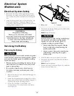
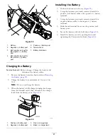
Page 40: ... machine Do not allow metal tools to short between the battery terminals and metal parts of the machine 1 Park the machine on a level surface and disengage the blade control switch 2 Ensure that the parking brake is engaged shut off the engine remove the key and wait for all moving parts to stop before leaving the operating position 3 Loosen the 2 fasteners on the battery cover counterclockwise 1 ...

Page 41: ...ged unplug the charger from the electrical outlet then disconnect the charger leads from the battery posts Figure 56 g000538 Figure 56 1 Positive battery post 3 Red charger lead 2 Negative battery post 4 Black charger lead Installing the Battery 1 Position the battery in the tray Figure 55 2 Using the fasteners previously removed install the positive red battery cable to the positive battery termi...

Page 42: ...of battery pull out the fuse and installed a new 25 A fuse Figure 58 g190588 Figure 58 1 Charge circuit 25 A Drive System Maintenance Checking the Tire Pressure Service Interval Every 25 hours Check tire pressure Maintain the air pressure in the front and rear tires as specified Uneven tire pressure can cause uneven cut Check the pressure at the valve stem Figure 59 Check the tires when they are c...

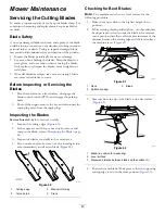
Page 43: ...ervice Interval Before each use or daily 1 Inspect the cutting edges Figure 60 2 If the edges are not sharp or have nicks remove and sharpen the blade refer to Sharpening the Blades page 44 3 Inspect the blades especially in the curved area 4 If you notice any cracks wear or a slot forming in this area immediately install a new blade Figure 60 g006530 Figure 60 1 Cutting edge 3 Wear slot forming 2...

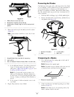
Page 44: ...t blade 6 Repeat this procedure on each blade Removing the Blades The blades must be replaced if a solid object is hit if the blade is out of balance or if the blade is bent For best performance and continued safety conformance of the machine use genuine Toro replacement blades Replacement blades made by other manufacturers may result in non conformance with safety standards 1 Hold the blade end u...

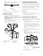
Page 45: ...ge 43 before continuing Level the mower deck side to side before adjusting the front to rear slope Requirements The machine must be on a level surface All 4 tires must be properly inflated refer to Checking the Tire Pressure page 42 Checking the Side to Side Level The mower blades must be level from side to side Check the side to side level any time you install the mower or when you see an uneven ...

Page 46: ...e rear blade tip continue to the Leveling the Mower Deck page 46 procedure g007199 Figure 70 1 Blades front to rear 3 Measure from the tip of the blade to the flat surface here 2 Outside cutting edges Leveling the Mower Deck 1 Set the anti scalp rollers to the top holes or remove them completely for this procedure refer to Adjusting the Anti Scalp Rollers page 24 2 Set the height of cut lever to t...

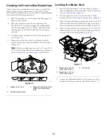
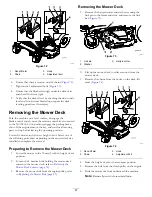
Page 47: ... depending on the mower deck size installed to complete the removal Preparing to Remove the Mower Deck 1 Lower the mower to the 76 mm 3 inches height of cut position 2 Loosen the 2 bottom bolts holding the mower deck curtain to the mower deck refer to Releasing the Mower Deck Curtain page 33 3 Remove the mower belt from the engine pulley refer to Replacing the Mower Belt page 49 Removing the Mower...

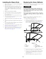
Page 48: ...ng the mower deck curtain to the mower deck refer to Releasing the Mower Deck Curtain page 33 Replacing the Grass Deflector Service Interval Before each use or daily Inspect the grass deflector for damage WARNING An uncovered discharge opening could allow the lawn mower to throw objects at you or bystanders and result in serious injury Also contact with the blade could occur Never operate the lawn...

Page 49: ...ck the belts for wear or cracks Check the belts for cracks frayed edges burn marks or any other damage Replace damaged belts Replacing the Mower Belt Squealing when the belt is rotating blades slipping when cutting grass frayed belt edges burn marks and cracks are signs of a worn mower belt Replace the mower belt if any of these conditions are evident 1 Disengage the blade control switch PTO move ...

Page 50: ... Install the mower deck curtain refer to Releasing the Mower Deck Curtain page 33 Cleaning Washing the Underside of the Mower Service Interval After each use Clean the mower deck housing Important You can wash the machine with a mild detergent and water Do not pressure wash the machine Avoid excessive use of water especially near the control panel under the seat around the engine hydraulic pumps a...

Page 51: ...m the outside of the engine cylinder head fins and blower housing Important You can wash the machine with mild detergent and water Do not pressure wash the machine Avoid excessive use of water especially near the control panel engine hydraulic pumps and motors 3 Check the parking brake operation refer to Operating the Parking Brake page 18 4 Service the air cleaner refer to Servicing the Air Clean...

Page 52: ...rt that is damaged 12 Paint all scratched or bare metal surfaces Paint is available from your Authorized Service Dealer 13 Store the machine in a clean dry garage or storage area Remove the key from the ignition switch and keep it out of reach of children or other unauthorized users Cover the machine to protect it and keep it clean 52 ...

Page 53: ... lever to On 3 The air cleaner is dirty 3 Clean or replace the air cleaner element 4 The spark plug wire s is loose or disconnected 4 Install the wire s on the spark plug 5 The spark plug s is pitted fouled or the gap is incorrect 5 Install a new correctly gapped spark plug s 6 There is dirt in fuel filter 6 Replace the fuel filter 7 Dirt water or stale fuel is in fuel system 7 Contact an Authoriz...

Page 54: ...bration 6 A blade spindle is bent 6 Contact an Authorized Service Dealer 1 The blade s is not sharp 1 Sharpen the blade s 2 A cutting blade s is are bent 2 Install a new cutting blade s 3 The mower is not level 3 Level the mower from side to side and front to rear 4 An anti scalp wheel is not set correctly 4 Adjust the anti scalp wheel height 5 The underside of the mower is dirty 5 Clean the under...

Page 55: ...Schematics g203461 Electrical Diagram Rev A 55 ...

Page 56: ...Notes ...

Page 57: ...Notes ...

Page 58: ...Notes ...

Page 59: ...f these activities We will not sell your personal information to any other company We reserve the right to disclose personal information in order to comply with applicable laws and with requests by the appropriate authorities to operate our systems properly or for our own protection or that of other users Retention of your Personal Information We will keep your personal information as long as we n...

Page 60: ...dure 1 Contact your seller to arrange service of the product If for any reason it is impossible for you to contact your seller you may contact any Toro Authorized Distributor to arrange service Visit http www toro com en us locator pages default aspx to locate a Toro distributor in your area 2 Bring the product and your proof of purchase sales receipt to the servicing outlet If for any reason you ...

Reviews: