background image

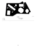
Choke Control

Use the choke control to start a cold engine.

Hour Meter

The hour meter records the number of hours the
engine has operated. It operates when the engine
is running. Use these times for scheduling regular
maintenance (

Figure 6

).

Motion-Control Levers

Use the motion-control levers to drive the machine
forward, reverse, and turn either direction (

Figure 5

).

Neutral-Lock Position

Move the motion-control levers outward from the
center to the N

EUTRAL

-

LOCK

position when exiting

the machine (

Figure 23

). Always position the

motion-control levers into the N

EUTRAL

-

LOCK

position

when you stop the machine or leave it unattended.

Parking-Brake Lever

The parking-brake lever is located on the left side of
the console (

Figure 5

). The brake lever engages a

parking brake on the drive wheels.

To engage the parking brake, pull up the lever until it
latches into the detent slot.

To disengage the parking brake, pull the lever out of
the detent slot and toward you, then push it down.

Foot Pedal Deck-Lift System

The foot pedal deck-lift system allows you to lower
and raise the deck from the seated position. You
can use the foot pedal to lift the deck briefly to avoid
obstacles or lock the deck in the highest height of cut
or transport position (

Figure 5

).

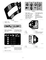
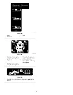
Smart Speed

Control System

Lever

The Smart Speed

Control-System lever, located

below the operating position, gives you a choice to
drive the machine at 3 speed ranges— trim, tow, and
mow (

Figure 26

).

12 V Power Point

Use the power point to power 12 V accessories
(

Figure 6

).

Important:

When not using the 12 V power point,

insert the rubber plug to prevent damage to the
power point.

Key Switch

The key switch, used to start and shut off the engine,
has 3 positions: O

FF

, R

UN

, and S

TART

. Refer to

Starting the Engine (page 22)

.

Blade-Control Switch (Power
Takeoff)

The blade-control switch, represented by a
power-takeoff (PTO) symbol, engages and
disengages power to the mower blades (

Figure 6

).

Height-of-Cut Lever

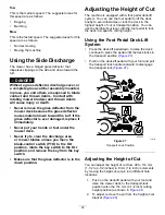
The height-of-cut lever works with the foot pedal to
lock the deck in a specific cutting height. Adjust the
height of cut only when the machine is not moving
(

Figure 5

).

Attachments/Accessories

A selection of Toro approved attachments and
accessories is available for use with the machine
to enhance and expand its capabilities. Contact
your Authorized Service Dealer or authorized Toro
distributor or go to www.Toro.com for a list of all
approved attachments and accessories.

To ensure optimum performance and continued safety
certification of the machine, use only genuine Toro
replacement parts and accessories. Replacement
parts and accessories made by other manufacturers
could be dangerous, and such use could void the
product warranty.

12


Summary of Contents for TimeCutter HD MyRide 75211

Page 1: ...ter HD MyRide 48in 54in or 60in Riding Mower Model No 75211 Serial No 402000000 and Up Model No 75212 Serial No 402000000 and Up Model No 75213 Serial No 402000000 and Up Register at www Toro com Original Instructions EN 3417 438 B ...

Page 2: ...altitudes otherwise you could overheat and damage the engine If you are unsure whether or not your machine has been converted for high altitude use look for the following label decal127 9363 Introduction This rotary blade riding lawn mower is intended to be used by homeowners in residential applications It is designed primarily for cutting grass on well maintained lawns Read this information caref...

Page 3: ...the Anti Scalp Rollers 26 Using Attachments and Accessories 27 Operating Tips 27 After Operation 28 After Operation Safety 28 Pushing the Machine by Hand 30 Maintenance 31 Maintenance Safety 31 Recommended Maintenance Schedule s 32 Engine Maintenance 33 Engine Safety 33 Servicing the Air Cleaner 33 Servicing the Engine Oil 34 Servicing the Spark Plug 37 Cleaning the Cooling System 38 Fuel System M...

Page 4: ...hrowing objects Toro designed and tested this lawn mower to offer reasonably safe service however failure to comply with safety instructions may result in injury or death Read understand and follow all instructions and warnings in the Operator s Manual and other training material on the machine engine and attachments All operators and mechanics should be trained If the operator s or mechanic s can...

Page 5: ...rees Use the slope chart to determine the degree of slope of hills before operating Do not operate this machine on a slope greater than 15 degrees Fold along the appropriate line to match the recommended slope 2 Align this edge with a vertical surface a tree building fence pole etc 3 Example of how to compare slope with folded edge 5 ...

Page 6: ...symbols are on your battery 1 Explosion hazard 6 Keep bystanders away from the battery 2 No fire open flame or smoking 7 Wear eye protection explosive gases can cause blindness and other injuries 3 Caustic liquid chemical burn hazard 8 Battery acid can cause blindness or severe burns 4 Wear eye protection 9 Flush eyes immediately with water and get medical help fast 5 Read the Operator s Manual 10...

Page 7: ...fore performing maintenance 2 Height of cut selection decal132 0872 132 0872 1 Thrown object hazard keep bystanders away from the machine 3 Severing hazard of hand or foot keep away from moving parts 2 Thrown object hazard raised baffle do not operate the machine with an open deck use a bagger or a baffle 4 Entanglement hazard keep away from moving parts keep all guards and shields in place decal1...

Page 8: ...ssure every 25 operating hours 4 Check the tire pressure every 25 operating hours 2 Engine oil 5 Read the Operator s Manual before performing maintenance 3 Check the tire pressure every 25 operating hours decal136 9186 136 9186 1 Read the Operator s Manual before adding weight to the bucket 8 ...

Page 9: ...e 1 Warning read the Operator s Manual 3 Cutting dismemberment hazard of the hand mower blade entanglement hazard of the hand belt stay away from moving parts keep all guards and shields in place 5 Ramp hazard do not use dual ramps when loading onto a trailer use 1 ramp wide enough for the machine use a ramp with a slope less than 15 back up the ramp when loading the machine and drive forward off ...

Page 10: ...decal133 9263 133 9263 1 Fast 4 PTO disengage 2 Slow 5 PTO engage 3 Choke 10 ...

Page 11: ...with all the controls before you start the engine and operate the machine Control Panel g188738 Figure 6 1 Hour meter 4 Key switch 2 Throttle control 5 Blade control switch power takeoff 3 Choke control 6 12 V power point Fuel Gauge The fuel gauge displays the amount of fuel in the tank Figure 7 g238298 Figure 7 1 Fuel gauge 2 Fuel tank cap Throttle Control The throttle controls the engine speed a...

Page 12: ...Figure 5 Smart Speed Control System Lever The Smart Speed Control System lever located below the operating position gives you a choice to drive the machine at 3 speed ranges trim tow and mow Figure 26 12 V Power Point Use the power point to power 12 V accessories Figure 6 Important When not using the 12 V power point insert the rubber plug to prevent damage to the power point Key Switch The key sw...

Page 13: ...y switches and shields are attached and functioning properly Do Not operate unless they are functioning properly Do Not operate the mower when people especially children or pets are in the area Stop the machine and attachment s if anyone enters the area Do Not operate the machine without the entire grass collection system discharge deflector or other safety devices in place and in proper working c...

Page 14: ...ors A fire or explosion from gasoline can burn you and others and cause property damage Always place gasoline containers on the ground away from your vehicle before filling Do Not fill gasoline containers inside a vehicle or on a truck or trailer bed because interior carpets or plastic truck bed liners may insulate the container and slow the loss of any static charge When practical remove gas powe...

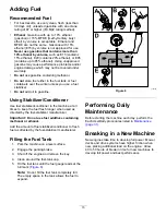
Page 15: ...lizer conditioner in the machine at all times to keep the fuel fresh longer when used as directed by the fuel stabilizer manufacturer Important Do not use fuel additives containing methanol or ethanol Add the amount of fuel stabilizer conditioner to fresh fuel as directed by the fuel stabilizer manufacturer Filling the Fuel Tank 1 Park the machine on a level surface 2 Engage the parking brake 3 Sh...

Page 16: ...ngine the engine should not crank 2 Sit on the seat engage the parking brake and move the blade control switch PTO to the OFF position Move either motion control lever out of the NEUTRAL LOCK position Try starting the engine the engine should not crank Repeat for other control lever 3 Sit on the seat engage the parking brake move the blade control switch PTO to the OFF position and move the motion...

Page 17: ...or the rear shock assemblies have detent positions for reference You can position the rear shock assemblies anywhere in the slot not just in the detent positions The following graphic shows the position for a soft or firm ride and the different detent positions Figure 10 g195744 Figure 10 1 Firmest position 3 Detents in the slots 2 Softest position Note Ensure that the left and right rear shock as...

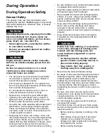
Page 18: ... balance or footing Be sure all drives are in neutral and parking brake is engaged before starting engine Start the engine carefully according to instructions with feet well away from the blades Never operate the mower with damaged guards shields or covers Always have safety shields guards switches and other devices in place and in proper working condition Keep clear of the discharge opening at al...

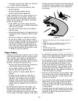
Page 19: ...e and good judgment when performing this evaluation Changes in the terrain such as moisture can quickly affect the operation of the machine on a slope Identify hazards at the base of the slope Do Not operate the machine near drop offs ditches embankments water or other hazards The machine could suddenly roll over if a wheel goes over the edge or the edge collapses Keep a safe distance twice the wi...

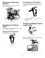
Page 20: ... Park the machine on a level surface g188778 Figure 14 Disengaging the Parking Brake To disengage the parking brake pull the lever out of the detent slot and toward you then push it down Figure 15 g188777 Figure 15 1 Push the parking brake out of the detent slot and toward you 2 Push the parking brake down Engaging the Blade Control Switch PTO g008945 Figure 16 Note Always engage the blades with t...

Page 21: ...he PTO g187517 Figure 19 Operating the Choke Use the choke to start a cold engine 1 Pull up the choke knob to engage the choke before using the key switch Figure 20 Note Ensure that you fully engage the choke You may need to hold the knob up when you use the key switch 2 Push down the choke to disengage the choke after the engine has started Figure 20 g008959 Figure 20 1 ON position 2 OFF position...

Page 22: ...ure 21 2 Turn the key to the STOP position to shut off the engine Starting the Engine Note A warm or hot engine may not require choking Important Do not engage the starter for more than 5 seconds at a time Engaging the starter motor for more than 5 seconds can damage the starter motor If the engine fails to start wait 10 seconds before operating the engine starter again g189354 Figure 22 Shutting ...

Page 23: ...ime for you to adapt to how it moves The throttle control regulates the engine speed as measured in rpm revolutions per minute Place the throttle control in the FAST position for best performance Always operate in the full throttle position when mowing WARNING The machine can spin very rapidly You may lose control of the machine and cause personal injury or damage to the machine Use caution when m...

Page 24: ...gure 26 1 Smart speed lever To change speeds do the following 1 Move the motion control levers to neutral and outward to the NEUTRAL LOCK position 2 Disengage the blade control switch 3 Adjust the lever to the desired position The following are only recommendations for use Adjustments vary by grass type moisture content and the height of the grass Suggested uses Trim Tow Mow Parking X Heavy wet gr...

Page 25: ...ey from the key switch Make sure that the grass deflector is in the down position Adjusting the Height of Cut The machine is equipped with a foot pedal deck lift system You can use the foot pedal to lift the deck briefly to avoid obstacles or lock the deck in the highest height of cut or transport position You can use the height of cut lever with the foot pedal to lock the deck in a specific cutti...

Page 26: ... Scalp Rollers Whenever you change the height of cut adjust the height of the anti scalp rollers Note Adjust the anti scalp rollers so that the rollers do not touch the ground in normal flat mowing areas 1 Park the machine on a level surface disengage the blade control switch and engage the parking brake refer to Engaging the Parking Brake page 20 2 Shut off the engine remove the key and wait for ...

Page 27: ...lternating the Mowing Direction Alternate the mowing direction to keep the grass standing straight This also helps disperse clippings which enhances decomposition and fertilization Mowing at Correct Intervals Grass grows at different rates at different times of the year To maintain the same cutting height mow more often in early spring As the grass growth rate slows in mid summer mow less frequent...

Page 28: ...gnated tie down locations on the mower two on the left side and two on the right Figure 30 Use these locations even when transporting the mower with an attached accessory Using non designated locations may cause damage to the mower and or attachment g027708 Figure 30 1 Tie down location Secure a trailer to the towing vehicle with safety chains WARNING Driving on the street or roadway without turn ...

Page 29: ...hile driving the machine on a ramp as this could cause a loss of control or a tip over situation g027996 Figure 32 1 Full width ramp in stowed position 4 Ramp is at least four times 4X as long as the height of the trailer or truck bed to the ground 2 Side view of full width ramp in loading position 5 H height of the trailer or truck bed to the ground 3 Not greater than 15 degrees 6 Trailer Towing ...

Page 30: ...itch and engage the parking brake 2 Shut off the engine remove the key and wait for all moving parts to stop before leaving the operating position 3 Locate the bypass levers on the frame on both sides of the engine 4 Move the bypass levers forward through the key hole and down to lock them in place Figure 33 Note Do this for each lever 5 Turn the ignition key on and disengage the parking brake Not...

Page 31: ...ING Removal or modification of original equipment parts and or accessories may alter the warranty controllability and safety of the machine Unauthorized modifications to the original equipment or failure to use original Toro parts could lead to serious injury or death Unauthorized changes to the machine engine fuel or venting system may violate applicable safety standards such as ANSI OSHA and NFP...

Page 32: ...aner foam element more often in dusty dirty conditions Clean the paper air cleaner element more often in dirty or dusty conditions Change the engine oil and oil filter more often in dirty or dusty conditions Check the spark plug s Check the in line fuel filter Every 200 hours Replace the paper air cleaner element more often in dirty or dusty conditions Replace the spark plug s Replace the in line ...

Page 33: ...e extremely dusty or sandy Removing the Foam and Paper Elements 1 Park the machine on a level surface disengage the blade control switch PTO and engage the parking brake 2 Shut off the engine remove the key and wait for all moving parts to stop before leaving the operating position 3 Clean around the air cleaner cover to prevent dirt from getting into the engine and causing damage 4 Lift the cover...

Page 34: ...ce the paper air cleaner element more often in dirty or dusty conditions 1 Clean the paper element by tapping it gently to remove dust Note If it is very dirty replace the paper element with a new one 2 Inspect the element for tears an oily film or damage to the rubber seal 3 Replace the paper element if it is damaged Important Do not clean the paper filter Installing the Air Cleaner 1 Install the...

Page 35: ...sump 3 To keep dirt grass clippings etc out of the engine clean the area around the oil fill cap and dipstick before removing it Figure 38 g235263 Figure 38 Changing the Engine Oil and Oil Filter Service Interval After the first 5 hours After the first month whichever comes first Change the engine oil and filter Every 100 hours Yearly whichever comes first Change the engine oil and oil filter more...

Page 36: ... Note Ensure that the oil filter gasket touches the engine and then turn the filter an extra 3 4 turn g027477 Figure 40 6 Slowly pour approximately 80 of the specified oil into the filler tube and slowly add the additional oil to bring it to the Full mark Figure 41 36 ...

Page 37: ...emoving the Spark Plug 1 Park the machine on a level surface disengage the blade control switch PTO and engage the parking brake 2 Shut off the engine remove the key and wait for all moving parts to stop before leaving the operating position 3 Clean the area around the base of the plug to keep dirt and debris out of the engine 4 Remove the spark plug Figure 42 g027478 Figure 42 Checking the Spark ...

Page 38: ...lammable and highly explosive A fire or explosion from fuel can burn you and others and can damage property Refer to Adding Fuel page 15 for a complete list of fuel related precautions Replacing the In Line Fuel Filter Service Interval Every 100 hours Yearly whichever comes first Check the in line fuel filter Every 200 hours Every 2 years whichever comes first Replace the in line fuel filter Never...

Page 39: ...NING Incorrectly removing the cables from battery could damage the machine and cables causing sparks Sparks can cause the battery gasses to explode resulting in personal injury Always disconnect the negative black battery cable before disconnecting the positive red cable Always connect the positive red battery cable before connecting the negative black cable 1 Park the machine on a level surface d...

Page 40: ... battery from the chassis refer to Removing the Battery page 39 2 Charge the battery for a minimum of 1 hour at 6 to 10 A Note Do not overcharge the battery 3 When the battery is fully charged unplug the charger from the electrical outlet then disconnect the charger leads from the battery posts Figure 48 g000538 Figure 48 1 Positive battery post 3 Red charger lead 2 Negative battery post 4 Black c...

Page 41: ...of battery pull out the fuse and install a new 25 A fuse Figure 50 g190589 Figure 50 1 Charge circuit 25 A Drive System Maintenance Checking the Tire Pressure Service Interval Every 25 hours Check tire pressure Maintain the air pressure in the front and rear tires as specified Uneven tire pressure can cause uneven cut Check the pressure at the valve stem Figure 51 Check the tires when they are col...

Page 42: ...access the idler pulley 7 Using a spring removal tool Toro Part No 92 5771 remove the idler spring from the deck post to remove tension on the idler pulley Figure 52 g028279 Figure 52 1 Spring removal tool Toro Part No 92 5771 4 Idler arm 2 Idler spring 5 Mower belt 3 Deck post 8 Lower the mower to the lowest height of cut and place the height of cut pin in the lock position for the lowest height ...

Page 43: ...gage the parking brake 2 Shut off the engine remove the key and disconnect the spark plug wires from the spark plugs Inspecting the Blades Service Interval Before each use or daily 1 Inspect the cutting edges Figure 53 2 If the edges are not sharp or have nicks remove and sharpen the blade refer to Sharpening the Blades page 45 3 Inspect the blades especially in the curved area 4 If you notice any...

Page 44: ...The variance should be no more than 3 mm 1 8 inch g014973 Figure 57 1 Opposite blade edge in position for measuring 2 Level surface 3 Second measured distance between blade and surface B A If the difference between A and B is greater than 3 mm 1 8 inch replace the blade with a new blade refer to Removing the Blades page 45 and Installing the Blades page 45 Note If a bent blade is replaced with a n...

Page 45: ... at original angle 2 Check the balance of the blade by putting it on a blade balancer Figure 60 Note If the blade stays in a horizontal position the blade is balanced and can be used Note If the blade is not balanced file some metal off the end of the sail area only Figure 59 g000553 Figure 60 1 Blade 2 Balancer 3 Repeat this procedure until the blade is balanced Installing the Blades 1 Install th...

Page 46: ... 5 mm 3 16 inch an adjustment is required refer to Leveling the Mower Deck page 47 g229303 Figure 62 1 Blades side to side 3 Measure from the tip of the blade to the flat surface here 2 Outside cutting edges Checking the Front to Rear Blade Slope Check the front to rear blade level any time you install the mower If the front of the mower is more than 7 9 mm 5 16 inch lower than the rear of the mow...

Page 47: ... the rear edge of the cutting deck skirt 1 on each side of the cutting deck Figure 64 g010336 Figure 64 1 Wood block 6 6 cm 2 5 8 inches thick 3 Front edge 2 Wood block 7 3 cm 2 7 8 inches thick 5 Loosen the adjustment bolts on all 4 corners so that the deck is sitting securely on all 4 blocks Figure 65 g024313 Figure 65 1 Deck lift arm 3 Hook 2 Chain 4 Adjustment bolt 6 Ensure that there is tensi...

Page 48: ...f cut to the transport position 9 Remove the belt from the clutch pulley on the engine 10 Slide the mower out from underneath the machine Note Retain all parts for future installation Installing the Mower Deck 1 Park the machine on a level surface disengage the blade control switch PTO and engage the parking brake 2 Shut off the engine remove the key and disconnect the spark plug wires from the sp...

Page 49: ...ector with the bracket ends between the welded brackets on the deck as shown in Figure 69 4 Install the spring onto the straight end of the rod 5 Position the spring on the rod as shown in Figure 69 so that the shorter spring end comes from under the rod before the bend and going over the rod as it returns from the bend 6 Lift the loop end of the spring and place it into the notch on the deflector...

Page 50: ...inch decks 5 Hose 3 Washout fitting 4 Lower the mower to the lowest height of cut 5 Sit on the seat and start the engine 6 Engage the blade control switch and let the mower run for 1 to 3 minutes 7 Disengage the blade control switch PTO shut off the engine remove the key from the key switch and wait for all moving parts to stop 8 Turn the water off and remove the coupling from the washout fitting ...

Page 51: ...ng 10 Check the condition of the blades refer to Servicing the Cutting Blades page 43 11 Prepare the machine for storage when non use occurs over 30 days Prepare the machine for storage as follows A Add a petroleum based stabilizer conditioner to fuel in the tank Follow mixing instructions from the stabilizer manufacturer Do not use an alcohol based stabilizer ethanol or methanol Note A fuel stabi...

Page 52: ... that the voltage is 12 4 V or higher Note If the battery voltage is below 12 4 V repeat steps 1 and 2 Battery Storage Tips Store the battery in a cool dry area in an upright position Do not stack batteries directly on top of each other unless they are in cartons Do not stack more than 3 batteries only 2 if the battery type is commercial Test a wet battery every 4 to 6 months and charge it if nece...

Page 53: ...Move the choke lever to the ON position 3 The air cleaner is dirty 3 Clean or replace the air cleaner element 4 The spark plug wire s is loose or disconnected 4 Install the wire s on the spark plug 5 The spark plug s is pitted fouled or the gap is incorrect 5 Install a new correctly gapped spark plug s 6 There is dirt in fuel filter 6 Replace the fuel filter 7 Dirt water or stale fuel is in fuel s...

Page 54: ...ne vibrates abnormally 7 The motor mount is loose or worn 7 Contact an Authorized Service Dealer 1 The blade s is not sharp 1 Sharpen the blade s 2 A cutting blade s is are bent 2 Install a new cutting blade s 3 The mower is not level 3 Level the mower from side to side and front to rear 4 An anti scalp roller if applicable is not set correctly 4 Adjust the anti scalp wheel height 5 The underside ...

Page 55: ...Schematics g289095 Electrical Diagram Rev A 55 ...

Page 56: ......

Reviews: