background image

Service Dealer’s Guide to Great Quality of Cut

4 - 13 

Checking and Adjusting the Blade Level

4.

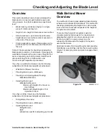
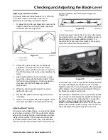
To adjust the front-to-rear pitch, loosen the front 
pivot plate mounting bolts slightly (Figure 44).

Figure 44

XL38pit2.TIF

5.

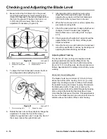
Rotate lock nuts on eyebolts to change the 
adjustment. To raise the front of the mower, 
tighten the eyebolt lock nuts. To lower the front of 
the mower, loosen the eyebolt lock nuts.

6.

After adjusting both eyebolt lock nuts evenly, 
check the front-to-rear pitch again. Continue 
adjusting until the blade pitch is within 
specification.

7.

Tighten the pivot plate mounting bolts.

8.

Recheck the side-to-side level and correct if 
necessary (see “Adjusting Side-to-Side Level—All 
Cutting Units” on page 4-10).

9.

Once the front-to-rear pitch and side-to-side level 
are within specification, continue by checking and 
adjusting the blade tracking (see “Adjusting Blade 
Tracking” on page 4-14).

44-inch (111.7cm) Cutting Unit

1.

Check side-to-side level and adjust as needed 
(see “Adjusting Side-to-Side Level—All Cutting 
Units” on page 4-10).

2.

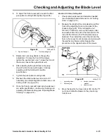
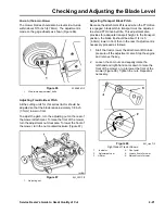
Measure the length of the rod extending out the 
front of the adjusting block on the sides of the 
chassis (Figure 45). If the rod length is not
5/8 inch (15.875mm), remove the hairpin cotter 
and washer from the end of the rod and turn the 
rod until the 5/8 inch (15.875mm) dimension is 
obtained. Then install the end of the rod into the 
hole in the mower mount and secure in place with 
the washer and hairpin cotter. Repeat this 
procedure on the opposite side of the mower.

Figure 45

XL44pit1.TIF

3.

Move the height of cut lever (deck lift) into the "C" 
notch and rotate the blades so they are facing 
front to rear. 

1.

Eye bolt locknut

2.

Pivot mounting bolt

1.

Adjusting block

2.

Adjusting rod

3. Hairpin cotter and 

washer

4. Mower mount

Summary of Contents for Recycler 20351

Page 1: ...MANUAL ...

Page 2: ... your Distributor Service Manager or us directly at the following address The Toro Company Consumer Service Department 8111 Lyndale Avenue South Bloomington MN 55420 1196 The Toro Company reserves the right to change product specifications or this manual without notice Copyright All Rights Reserved The Toro Company 2002 Bloomington MN 55420 1149 U S A ...

Page 3: ... Blade 3 2 Balancing the Blade 3 2 Installing the Blade 3 3 Checking and Adjusting the Blade Level Overview 4 1 Walk Behind Mower Overview 4 1 Riding Mower Overview 4 2 Checking Blade Level All Mowers 4 2 Preparing the Workspace 4 2 Measuring Blade Level 4 3 Checking and Adjusting Blade Tracking 4 4 Walk Behind Mowers 4 4 Riding Mowers 4 4 Adjusting Blade Level 4 4 Walk Behind Mowers 4 4 Specifica...

Page 4: ...s Front Engine Rider 4 9 Adjusting Side to Side Level All Cutting Units 4 10 Adjusting Front to Rear Pitch 4 11 32 inch 81 3cm Cutting Unit 4 11 38 inch 96 5cm Cutting Unit 4 12 44 inch 111 7cm Cutting Unit 4 13 Adjusting Blade Tracking 4 14 32 inch 81 3cm Cutting Unit 4 14 38 and 44 inch 96 5 and 111 7cm Cutting Units 4 15 260 Series Tractor 4 16 38 inch 96 5cm Mower 4 16 Adjusting Side to Side L...

Page 5: ... Cut General Troubleshooting Procedures 5 1 Specific Quality of Cut Problems and Possible Solutions 5 1 Blowout 5 1 Clumping 5 1 Clogged Chute Bagging or Side Discharging Only 5 2 Dribbling 5 2 Ragged Cut 5 2 Scalping 5 2 Stair Step or Sawtooth Cut 5 2 Stragglers 5 2 Streaking 5 2 Uncut Grass 5 3 Windrow 5 3 Kits to Improve Quality of Cut Toro Recycler Mulch Plug 6 1 Washout Port Kit P N 95 3282 6...

Page 6: ...iv Service Dealer s Guide to Great Quality of Cut This page intentionally left blank ...

Page 7: ...rovides an overview of the setup and operator instruction that promote a great quality of cut 3 Inspecting and Sharpening the Blade This section describes how to remove inspect sharpen balance and install a blade 4 Checking and Adjusting Blade Level This section describes how to check and adjust the blade level on all types of Toro and Lawn Boy brand rotary mowers built in 2002 5 Troubleshooting Q...

Page 8: ...1 2 Service Dealer s Guide to Great Quality of Cut This page intentionally left blank ...

Page 9: ...in the shop but must be resolved instead by a change in operating the mower Initial customer education is critical in preventing this situation If this situation arises after the customer has taken delivery of the mower a visit to the customer s lawn for demonstration of the problem and the suggested solution may be necessary Figure 2 5300 010 TIF Setup On all mowers proper mower setup consists of...

Page 10: ... these procedures are in the operator s manual Identify the machine s safety features and explain how they work and how to use them Remind the operator that safety instructions are in the operator s manual Demonstrate for the operator the sound of the engine operating under a normal load and then operating in an overloaded condition in which it is starting to bog down Show the operator how to clea...

Page 11: ...king discharged clippings The best height of cut varies with the type of grass and the season In the spring and fall when temperatures are moderate and rainfall is higher height of cut can usually be decreased In the summer when the temperature increases and rainfall decreases it is usually better to increase the height of cut To maintain the health of the grass turf grass agronomists recommend cu...

Page 12: ...2 4 Service Dealer s Guide to Great Quality of Cut This page intentionally left blank ...

Page 13: ...the engine and wait for all moving parts to stop 2 Disconnect the wire from the spark plug 3 Walk behind mowers Drain the fuel and oil from the engine Tip the mower on its side air filter up Riding mowers Remove the mower attachment or raise and block the tractor to allow access to the underside of the mower 4 Loosen the blade fastener s The blade fasteners differ from mower to mower Some mowers u...

Page 14: ... 6 Figure 6 sharpen TIF Balancing the Blade 1 Check the balance of the blade by placing the center hole of the blade over a nail or a screwdriver shank clamped horizontally in a vise Figure 7 Figure 7 balance1 TIF Note You can also check the balance using a commercially manufactured blade balancer such as the Magna Matic MAG 1000 Professional Blade Balancer Figure 8 Figure 8 mag1000 jpg Photo used...

Page 15: ...ranted Figure 9 MVC 713X jpg 2 Refer to the owner s manual for your particular unit for proper blade bolt nut torque Some common Toro Toro Wheel Horse and Lawn Boy torque values are shown in the following table Blade Bolt Nut Torque Guide for Lawn Boy Toro and Toro Wheel Horse Mowers built in 2002 Model ft lbs Nm Lawn Boy 21 inch walk behind mowers 47 63 Toro 21 inch and 22 inch walk behind mowers...

Page 16: ...3 4 Service Dealer s Guide to Great Quality of Cut This page intentionally left blank ...

Page 17: ... Walk Behind Mower Overview Checking Blade Level All Mowers Checking and Adjusting Blade Tracking Walk Behind Mowers Adjusting Blade Level Walk Behind Mowers Models with Height of Cut Lever on Each Wheel Models with Single Height of Cut Adjustment Lever If you have a riding mower see the following subsections for blade level adjustment procedures Riding Mower Overview Checking Blade Level All Mowe...

Page 18: ... Checking the blade level involves preparing a suitable workspace and measuring the distance from one of the blade tips to a level flat surface at the 12 3 6 and 9 o clock positions Preparing the Workspace Use a straight edge to verify that the workspace is flat Do not assume the floor is flat even if it appears to be so You will make measurements with a tolerance of less than 3 16 inch 5mm Figure...

Page 19: ...f the mower and the blade s Leave a space to write in your measurements Each blade must be measured at the 12 3 6 and 9 o clock positions Figure 14 and Figure 15 Figure 14 sketch1 TIF Figure 15 sketch2 TIF 3 If the desired height of cut is known make your measurements at this setting If this is not known set the mower in the middle of its height of cut HOC range 4 VERY IMPORTANT When you take the ...

Page 20: ...ing Housings with cut outs are more difficult to check Verify all other measurements when checking these mowers If there is a large difference in the measurement from one area to another the mower housing may be bent at the point where the engine or blade spindle mounts You can correct for this by placing shim washers between the engine or spindle and the housing Check for level after installing s...

Page 21: ... cut it has lost spring tension and must be replaced When the height of cut spring arm is weak and has slipped a number of times it can wear away the notches On steel decks the height of cut plate should be replaced if this happens On cast decks this wear is in the deck housing itself One alternative is to replace the deck housing However there are two wear plate kits which fit many 21 inch Toro m...

Page 22: ...ise it to the position of the other front wheel After reinstalling the wheel and pivot verify that the blade is level side to side Adjusting Side to Side Level If the blade is not level within 1 8 inch 3 1mm side to side the engine will need to be shimmed Loosen the engine mounting screws on the low side of the blade Slip a washer or other shim material between the engine and housing Figure 24 On ...

Page 23: ...o the mower housing Insert the shim between the cap and housing and install the cap screws Figure 26 Figure 26 p2260004 JPG Adjusting Side to Side Level Loosen the engine mounting screws on the side where the blade is low Figure 27 Temporarily insert a washer between the engine and mower housing and re measure the blade If it is now level remove the engine mounting screw and re install through the...

Page 24: ...he parts as necessary Adjusting Front to Rear Pitch The blade should be 7 16 inch 10 9mm lower when it passes the front of the mower than when it passes the rear This measurement can be between 1 8 inch 3 1mm and 1 2 inch 12 7mm low in front If the difference is out of this range the mower suspension is either worn or bent Straighten or replace as needed Adjusting Blade Tracking The blade should b...

Page 25: ...mm above the bottom of the housing If out of tolerance insert a washer or other shim between the spindle housing and mower housing Figure 33 Re measure the blade side to side If now correct remove the spindle housing bolt and re install through the housing shim and spindle Note that the blade tip will move more than the thickness of the shim Figure 33 MVC 732X JPG XL Series Front Engine Rider The ...

Page 26: ...cessary Remove the hairpin cotter and washer from the leveling bracket Figure 38 To level the blade s reposition the leveling bracket s in a different hole and install the washer and hairpin cotter Moving to a hole nearer the front lowers the blade height Moving to a hole nearer to the rear raises the height There are identical brackets on both sides Use the holes in both to level the blades side ...

Page 27: ...is Figure 40 If the rod length is not 5 8 inch 16mm remove the hairpin cotter and washer from the end of the rod and turn the rod until the 5 8 inch 16mm dimension is obtained Then install the end of the rod into the hole in the mower mount and secure it in place with the washer and hairpin cotter Repeat this process on the other side of the mower Figure 40 XL32pit2 TIF 3 Check the front to rear p...

Page 28: ... Once the front to rear pitch is within specification recheck the side to side adjustment see Adjusting Side to Side Level All Cutting Units on page 4 10 11 Once the front to rear pitch and side to side level are within specification continue by checking and adjusting the blade tracking see Adjusting Blade Tracking on page 4 14 38 inch 96 5cm Cutting Unit The blade pitch for a 38 inch 96 5cm mower...

Page 29: ...n specification continue by checking and adjusting the blade tracking see Adjusting Blade Tracking on page 4 14 44 inch 111 7cm Cutting Unit 1 Check side to side level and adjust as needed see Adjusting Side to Side Level All Cutting Units on page 4 10 2 Measure the length of the rod extending out the front of the adjusting block on the sides of the chassis Figure 45 If the rod length is not 5 8 i...

Page 30: ...to Side Level All Cutting Units on page 4 10 10 Check gage wheel height Each wheel should be approximately 3 8 inch 9 5mm off the ground Adjust as needed 11 Once the front to rear pitch and side to side level are within specification continue by checking and adjusting the blade tracking as follows Adjusting Blade Tracking The 32 inch 81 3cm cutting unit requires a blade tracking adjustment procedu...

Page 31: ...unts may be bent Figure 49 altbltrk TIF To check for a bent spindle remove the belt and spin the blade spindle Look at the center if it rotates in a tight circle the spindle is not bent If the center appears to wobble the spindle is bent and should be replaced Yet another way to check this with the blades attached is to align the blades two blades at a time on three blade mowers then run a string ...

Page 32: ...res to 12 psi 83kPa This mower attachment is adjustable in two ways One for higher heights of cut where the mower is suspended from the chassis and the other for lower positions where the level and height of cut are determined by the rear gage wheels In the 3 4 inch 7 6 10 1cm range the mower is suspended from the chassis The two outside blade tips should be an equal height from the ground within ...

Page 33: ...he jam nut Recheck side to side leveling 42 48 52 inch 106 6 121 9 132 0cm Mowers The side to level and front to rear pitch adjustments for all these models are the same However as you raise the cutting height the point at which the rear gage wheels comes off the ground is different for the 52 inch 132 0cm mower There is an adjustment process when the mower is suspended However if the gage wheels ...

Page 34: ...mower comes with one adjustable link standard although someone could have installed a second one The 48 inch and 52 inch 121 9cm and 132 0cm models have two adjustable links Figure 57 Figure 57 260XXF2R TIF 2 Rotate the bolt on front adjustable link s to change the blade pitch To raise the front of the mower shorten the adjustable link by turning bolt clockwise To lower front of mower turn bolt co...

Page 35: ...wer housing bolts and insert shim washers until the saddles are in line Then if you used washers to shim the spindle housing remove the bolt and reassemble through the washer to secure it 300 400 500 Series Garden Tractor Excluding 5xi Series The mower attachments used on these tractors all have the side to side level and the height of cut determined by the rear gage wheels Figure 60 Figure 60 138...

Page 36: ...nother way to check this with the blades attached is to align the blades two blades at a time on three blade mowers then run a string across the cutting tips of the blades The string should be straight If it is not the blade or spindle could be bent If the saddles or blades do not line up and the spindles are not bent a shim between the spindle housing and the mower housing may help align them Loo...

Page 37: ...Transport Blade Pitch Because the attachment lift is used when the PTO drive is engaged blade pitch in transport must be adjusted to extend PTO drive belt life This adjustment also provides for adequate transport height In the transport position the blade tip should be about 1 4 inch 6 3mm lower in front than in the rear If adjustment is necessary proceed as follows 1 Start the tractor lower the a...

Page 38: ...tring should be straight If it is not the blade or spindle could be bent If the saddles or blades do not line up and the spindles are not bent a shim between the spindle housing and the mower housing may help align them Loosen the spindle to mower housing bolts and insert shim washers until the saddles are in line Then if you used washers to shim the spindle housing remove the bolt and reassemble ...

Page 39: ...y do the blades need to be a minimum of 1 8 inch up from the bottom edge of the housing but they must also line up where the tips come together Take the two blade tips and point them towards each other They must be within 1 8 3 16 inch of level with each other or both must be the same distance from the blade to the ground Figure 74 Figure 74 trclevel TIF An alternate way to check this is to remove...

Page 40: ...4 24 Service Dealer s Guide to Great Quality of Cut This page intentionally left blank ...

Page 41: ...rive more slowly 4 Move over and take less than a full width cut 5 Check for grass build up in cutting chamber 6 Raise the height of cut and cut the lawn Come back a day or two later and re cut to the preferred height 7 Check for a sharp blade Sharpen as instructed in the Operator s Manual 8 Check for belt slippage on mowers using a belt in the blade drive system Toro BBC Riding Mowers and Wide Ar...

Page 42: ...ounce and this makes the outside edge dig into the ground Centrifugal force will apply in direct relation to the speed Stair Step or Sawtooth Cut Check mower for level side to side On multi blade mowers verify all blades are at the same height Stragglers 1 Check the blade pitch See the Operator s Manual or the section Checking and Adjusting the Blade Level of this manual for adjustment instruction...

Page 43: ...n the grass is too wet or too dry 11 On multi blade decks what is described as a streak can result from two of the blades not being aligned and therefore cutting at two different heights this is actually a stair step cut On multiple blade mowers the blade tips should be in line within 1 8 inch See the operator s manual or the section Checking and Adjusting the Blade Level of this manual for instru...

Page 44: ...5 4 Service Dealer s Guide to Great Quality of Cut This page intentionally left blank ...

Page 45: ...he accumulated grass can dry out and bond to the deck Once this happens the hard material must be scraped from under the deck This often removes the protective paint from under the deck With a washout port kit it is easy to hook up a garden hose and clean the cutting chamber after each use Many models currently have this kit factory installed However it can be used on most models by finding a plac...

Page 46: ...sed on garden tractor mowers to help keep the mower deck level when a vac bagger attachment is used Standard on 1997 and later vac baggers Baffle Kits Baffle kits are available for some mowers These are designed to help reduce the tendency to blow leaves and dry grass out the front of the mower If a mower has Recycler baffles and kickers try to resolve the blowout problem by removing these prior t...

Page 47: ...low is the movement of air created by the mower blade Air is pulled from under the lower edge of the cutting chamber This flow of air stands the grass up so the blade can cut it The grass clippings are then directed to the discharge opening bag or when mulching down onto the lawn The type and speed of blade shape of the housing and the amount of space for the air to enter and exhaust determine the...

Page 48: ...on a 21 inch blade rotating at 3 000 RPM Clumping wet grass when the clippings come out of the mower in bunches or piles If the clippings are stuck together moisture is usually the cause The moisture source can be either external rain or dew or internal dry ambient conditions but very lush grass clumpwet TIF Clumping dry grass similar in appearance to wet grass clumping but can occur in very dry c...

Page 49: ...e top of the grass blade after it is cut or from the ground to the cutting edge of the mower blade these should be the same Leveling the process of adjusting the mowing deck so that the blade is correctly positioned relative to the ground See the instructions for the particular mower for the correct adjustment method and measurements Lush grass grass with a high water content This is common in mos...

Page 50: ...rass raggdcut TIF Rake see Pitch Recycler Toro s patented mulching system Rough terrain terrain uneven enough to affect the quality of cut by causing the mower to bounce excessively terrain TIF Scalping when the blade cuts the grass at ground level or actually strikes the ground and removes earth scalp TIF Semi floating deck a type of mower that is partially supported by the chassis but also has w...

Page 51: ...hat is above ground but growing laterally rather than up sometimes combined with grass clippings that have not decomposed Some types of grass create little thatch others need the thatch to be removed periodically Thin Thick grass the density or the number of plants in a specific area The density of the grass is a factor in how much volume of grass the mower is asked to process and in how readily a...

Page 52: ...istent height of cut Wet grass grass that is wet to the touch Rain watering or morning dew can be the source of the moisture Windrow poor disbursement of clippings resulting in a nearly continuous line of cut grass clippings on the grass This may also appear as clumps of dry grass generally in a row across the lawn windrow TIF 1 3 Rule a recommendation by turf grass agronomists that not more than ...

Page 53: ...e measured but not so tall as to hit the top inside of the mower deck Wrap any kind of tape around one end and down far enough to reach the blade Reach under the housing place one end of the dowel on the ground and stand it upright Using the sharp edge of the blade make a mark in the tape Pull the dowel out and measure from the end to the mark That will be the height of cut MVC 728X jpg A smooth f...

Page 54: ...nt that you handle For ease of handling the board can be hinged in the middle This also allows storage in a smaller area To use the board cut a path with the mower being checked Place the board across the path and brush the grass with your hand Now stand back from the board and look at the grass against the reference line You will be able to see any uncut strips out of level or other quality of cu...

Page 55: ...rive in working order I Mower level front to rear Most tractors 1 8 inch low in front 32 inch mowers 20 inch and 21 inch walk behind mowers approximately 3 8 inch low in front 5 Observations from watching customer operating mower if possible 6 Check A Engine being run at full throttle B Cutting height of mower C Measured height of grass D Mowing speed suits conditions E Grass is wet or extremely l...

Page 56: ...7 10 Service Dealer s Guide to Great Quality of Cut This page intentionally left blank ...

Page 57: ...QUALITY OF CUT MANUAL Form No 492 4763 ...

Reviews: