background image

Form No. 3438-297 Rev B

Soft Side Bagger

ProLine Commercial Walk-Behind Mower

Model No. 139-7860

Installation Instructions

Safety

Safety and Instructional Decals

Safety decals and instructions are easily visible to the operator and are located near any area
of potential danger. Replace any decal that is damaged or missing.

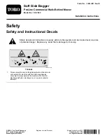
decal114-3489

114-3489

1.

Thrown object hazard; cutting/dismemberment hazard—do
not operate the machine with the discharge opening
uncovered; always operate the machine with the rear
discharge deflector, discharge cover, or grass collector
installed.

© 2020—The Toro® Company
8111 Lyndale Avenue South
Bloomington, MN 55420

Register at www.Toro.com.

Original Instructions (EN)

Printed in the USA

All Rights Reserved

*3438-297* B


Summary of Contents for ProLine 139-7860

Page 1: ...l danger Replace any decal that is damaged or missing decal114 3489 114 3489 1 Thrown object hazard cutting dismemberment hazard do not operate the machine with the discharge opening uncovered always...

Page 2: ...1 Bolt 3 8 x 3 4 inch 1 Locknut 3 8 inch 1 Left latch 1 Right latch 4 Phillips head screw 4 Locknut 10 4 Lock washer Procedure 1 Install the support on the back plate using 4 bolts 1 4 x 5 8 inch and...

Page 3: ...Frame Parts needed for this procedure 1 Bag and pan 1 Catcher frame 2 Handle 4 Bolt 1 4 x 1 inch 4 Locknut 1 4 inch 4 Washer 1 4 inch Procedure 1 Slide the upper curved portion of the bagger frame in...

Page 4: ...bolt 3 Nut 5 16 inch 1 Locknut 3 8 inch Procedure Note For 48 inch and 54 inch decks use the rounded edge discharge baffle for 36 inch and 60 inch decks use the square edge discharge baffle Figure 7...

Page 5: ...e 2 For 36 inch decks Bolt 3 8 x 1 inch for 60 inch decks Button head bolt 5 For 36 inch decks Locknut 3 8 inch for 60 inch decks Nut 5 16 inch 3 Nut 5 16 inch 3 For 48 inch and 54 inch decks Install...

Page 6: ...hine unless you install a mulch plate discharge deflector or grass collection system 6 Installing the Bagger onto the Machine No Parts Required Procedure 1 Position the front and rear tab on the bagge...

Page 7: ...pins into them Figure 13 8 Lower the latches to secure the bagger g002161 Figure 13 1 Back plate holes 3 Latch 2 Frame pin 4 Lower pin Product Overview g315746 Figure 14 1 Bagger Specifications Machi...

Page 8: ...er the latches to secure the bagger Clearing Obstructions 1 Disengage the PTO and engage the parking brake 2 Shut off the engine remove the key and wait for all moving parts to stop before leaving the...

Page 9: ...bagger attachment Cleaning the Bagger Service Interval Before each use or daily Clean the bagger after each use 1 Remove the bag and wash the back plate and the underside of the machine Use a mild aut...

Page 10: ...Notes...

Page 11: ...Notes...

Page 12: ......

Reviews: