background image

g008238

Figure 31

1.

Drive-belt cover

6.

Drive belt

2.

Bolt (3)

7.

Rotor shaft

3.

Rotor-pulley bolt

8.

Brake spring (unhook from
idler arm here)

4.

Curved washer

9.

Idler pulley

5.

Rotor pulley

10.

Engine pulley

2.

Unhook the brake spring from the idler arm to
release the belt tension (

Figure 31

).

3.

Remove the screw and curved washer that
holds the rotor pulley (

Figure 31

).

4.

Remove the rotor pulley and the drive belt
(

Figure 31

).

5.

Install the new drive belt, routing it as shown in

Figure 32

.

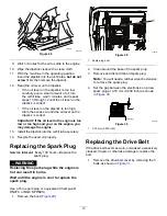
g008317

Figure 32

1.

Brake spring (install on
idler arm here)

3.

Engine pulley

2.

Idler pulley

4.

Rotor pulley

Note:

Route the new drive belt first around the

engine pulley, then the idler pulley, and finally
around the loose rotor pulley positioned just
above the rotor shaft (

Figure 31

).

6.

Install the rotor pulley onto the rotor shaft (

Figure

31

).

7.

Install the curved washer and the rotor-pulley
bolt and tighten them securely (

Figure 31

).

Note:

The concave side of the curved washer

goes against the outside of the pulley.

8.

Install the brake spring onto the idler arm (

Figure

32

).

9.

Install the drive-belt cover with the bolts that you
removed in step

1

.

Note:

Ensure that the drive belt is properly

adjusted and operating; refer to

Checking the

Control Cable (page 16)

and

Adjusting the

Control Cable (page 17)

.

Adjusting the Quick Shoot
Control

Model 38756

If there is more than 13 mm (1/2 inch) of slack in the
Quick Shoot cable (

Figure 33

or the discharge chute

does not rotate left and right in equal angles, adjust
the Quick Shoot control cables.

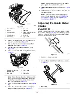
g006514

Figure 33

1.

13 mm (1/2 inch) maximum slack

1.

Loosen the 2 Quick Shoot control-cable clamps
(

Figure 34

).

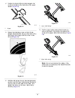
g286559

Figure 34

1.

Cable clamps

20


Summary of Contents for Power Clear 721

Page 1: ...sages identified by the safety alert symbol Figure 2 which signals a hazard that may cause serious injury or death if you do not follow the recommended precautions g000502 Figure 2 Safety alert symbol This manual uses 2 words to highlight information Important calls attention to special mechanical information and Note emphasizes general information worthy of special attention Important If you are ...

Page 2: ...chments Accessories 8 Operation 9 Before Operation 9 Before Operation Safety 9 Filling the Fuel Tank 9 Checking the Engine Oil Level 10 During Operation 11 During Operation Safety 11 Starting the Engine 11 Engaging the Rotor Blades 13 Disengaging the Rotor Blades 13 Shutting Off the Engine 13 Adjusting the Discharge Chute and Chute Deflector 13 Adjusting the Discharge Chute and Chute Deflector 13 ...

Page 3: ...e engine Ensure that everyone using this product knows how to use it knows how to shut off the engine quickly and understands the warnings Shut off the engine whenever you leave the operating position for any reason Do not put your hands or feet near moving parts on the machine Do not operate the machine without all guards and other safety protective devices in place and working Keep clear of any ...

Page 4: ...ecal133 8061 133 8061 decal139 3505 139 3505 1 Insert the key press the primer 3 times move the choke lever to the left pull the recoil start handle and once the engine is running move the choke lever to the right 4 Thrown object hazard keep bystanders away 2 Warning read the Operator s Manual 5 Read the Operator s Manual before servicing the engine oil level 3 Explosion hazard do not tip the mach...

Page 5: ...Setup 1 Unfolding the Handle No Parts Required Procedure g287663 2 Installing the Recoil Start Guide and Rope No Parts Required Procedure g286483 5 ...

Page 6: ...3 Installing the Discharge Chute No Parts Required Procedure Models 38752 and 38753 g291515 Model 38756 g262492 6 ...

Page 7: ...4 Filling the Engine with Oil No Parts Required Procedure g286445 5 Adjusting the Control Cable No Parts Required Procedure Refer to Adjusting the Control Cable page 17 7 ...

Page 8: ...hoke Specifications Model Weight Length Width Height 38 kg 38752 84 lb 38 kg 122 cm 54 cm 107 cm 38753 84 lb 39 kg 38756 86 lb 48 inches 21 inches 42 inches Attachments Accessories A selection of Toro approved attachments and accessories is available for use with the machine to enhance and expand its capabilities Contact your Authorized Service Dealer or authorized Toro distributor or go to www To...

Page 9: ...an object Fill the fuel tank outdoors when the engine is cold Replace the fuel cap securely and wipe up spills Do not handle fuel when smoking or around an open flame or sparks Store fuel in an approved fuel container out of the reach of children When fuel is in the tank tip the machine only as directed in the instructions If you spill fuel on your clothing change your clothing immediately Filling...

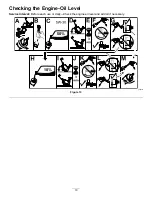
Page 10: ...Checking the Engine Oil Level Service Interval Before each use or daily Check the engine oil level and add oil if necessary g286445 Figure 13 10 ...

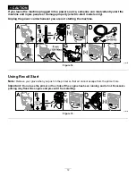
Page 11: ... engine indoors exhaust fumes are dangerous Do not overload the machine capacity by attempting to clear snow at too fast a rate Shut off the engine whenever you leave the operating position before clearing or unclogging the collector rotor or discharge chute and when making any repairs adjustments or inspections Starting the Engine Using Electric Start Electric start models only Note Remove your g...

Page 12: ...plug the power cord whenever you are not starting the machine g280288 Figure 14 Using Recoil Start Note Remove your glove when you push in the primer so that air cannot escape from the primer hole Important Do not use the primer or the choke if the engine has been running and is hot Excessive priming may flood the engine and prevent it from starting g280295 Figure 15 12 ...

Page 13: ...ise or lower the angle of the chute deflector press the trigger on the chute deflector and move the chute deflector up or down To adjust the discharge chute move the chute handle g278630 Figure 18 1 Chute handle 2 Trigger Adjusting the Discharge Chute and Chute Deflector Model 38756 To adjust the discharge chute press the trigger of the Quick Shoot control on the right side of the handle and move ...

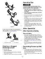
Page 14: ...ssible If the machine does not propel itself forward on slippery surfaces or in heavy snow push forward on the handle but allow the machine to work at its own pace The machine may leave rubber marks on new brushed or light colored concrete Test on an inconspicuous location before use These marks are not permanent After Operation After Operation Safety General Safety Never store the machine with fu...

Page 15: ...he machine and push the electric start button once to prevent the recoil starter and or the electric starter from freezing up electric start models only In snowy and cold conditions some controls and moving parts may freeze Do not use excessive force when trying to operate frozen controls If you have difficulty operating any control or part start the engine and let it run for a few minutes 15 ...

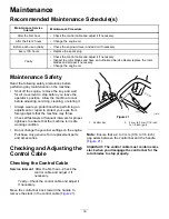
Page 16: ...ing or storing it Always wear eye protection while performing an adjustment or repair to protect your eyes from foreign objects that the machine may throw Check all fasteners at frequent intervals for proper tightness to ensure that the machine is in safe working condition Do not change the governor settings on the engine Purchase only genuine Toro replacement parts and accessories Checking and Ad...

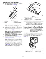
Page 17: ...eavy load disconnect the spring from the adjustor link and move the upper end of the spring to the hole that is further from the pivot point in the control bar Figure 23 Then connect the spring to the adjustor link and adjust the control cable g006587 Figure 23 1 Remove the upper end of spring from this hole 3 Pivot point 2 Insert the upper end of spring into this hole 4 Upper end of spring Note T...

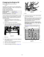
Page 18: ...lace an oil drain pan under the oil drain plug remove the plug and tip the machine backward and drain the used oil in the pan Figure 25 g286519 Figure 25 1 Oil drain plug 4 After draining the used oil return the machine to the operating position 5 Install the oil drain plug and tighten it securely 6 Clean around the oil fill dipstick 7 Unscrew the dipstick and remove it Figure 26 g006316 Figure 26...

Page 19: ...l the dipstick into the oil fill tube securely 14 Recycle the used oil properly Replacing the Spark Plug Service Interval Every 100 hours Replace the spark plug WARNING Replacing the spark plug while the engine is hot can result in burns Wait until the engine is cool to replace the spark plug Use a Toro spark plug or equivalent Champion RN9YC or NGK BPR6ES 1 Remove the boot Figure 29 g030123 Figur...

Page 20: ... above the rotor shaft Figure 31 6 Install the rotor pulley onto the rotor shaft Figure 31 7 Install the curved washer and the rotor pulley bolt and tighten them securely Figure 31 Note The concave side of the curved washer goes against the outside of the pulley 8 Install the brake spring onto the idler arm Figure 32 9 Install the drive belt cover with the bolts that you removed in step 1 Note Ens...

Page 21: ... discharge chute in the straight ahead position pull the lower cable casing downward until you remove the slack in the cable and tighten the screw on the lower cable clamp securely Figure 37 g286565 Figure 37 1 Lower cable casing 5 Pull the upper cable casing forward until you remove the slack in the cable and tighten the screw on the upper cable clamp securely Figure 38 g286566 Figure 38 1 Upper ...

Page 22: ... engine for 10 minutes to distribute the conditioned fuel through the fuel system 3 Shut off the engine allow it to cool and siphon the fuel tank or run the engine until it shuts off 4 Start the engine and run it until it shuts off 5 Choke or prime the engine start it a third time and run the engine until it does not start 6 Drain the fuel in the carburetor through the carburetor drain bolt into a...

Page 23: ...to restaurants grocery stores hotels schools and hospitals and on a wide variety of products Additionally some online and mail order retailers provide Prop 65 warnings on their websites or in catalogs How do the California warnings compare to federal limits Prop 65 standards are often more stringent than federal and international standards There are various substances that require a Prop 65 warnin...

Page 24: ......

Reviews: