background image

2. 

Remove the capscrews securing the battery tray to
the machine and slide the tray out (Fig. 51).

3. 

Check both batteries for charge with a hydrometer.
If the batteries check acceptably, slide the tray back
in place, secure with capscrews and install the side
panel. If the batteries require charging, proceed to
step 4.

4. 

Remove the negative (–) battery cable connectors
from the batteries (Fig. 51). Connect a 3- to 4-amp
battery charger to the posts. Charge the batteries at a
rate of 3 to 4 amperes for 4 to 8 hours.

Figure 51

1.

Battery tray 

2.

Negative (–) cable connectors

5. 

When batteries are fully charged, disconnect charger
from electrical outlet and battery posts.

6.

Connect the negative (–) cable ends, slide the tray
back in place, and secure it with capscrews. Install
the side panel, close the hood and secure both with
latches.

FUSES & CIRCUIT BREAKER

One 5 amp, two 15-amp fuses and a fusible link are
incorporated for the protection of the entire wiring circuit.
The link can be replaced if the total loss of electrical
function results. They are located under the control panel to
the right of the seat (Fig. 52). If total loss of electrical
function occurs, find and correct the malfunction before
replacing the fusible link.

Figure 52

1.

Fuse block

IMPORTANT: Do not install the fuses in the fuse block
on the left side of the instrument control panel. Fuses
should be installed in this fuse block only if the machine
is equipped with a road light kit.

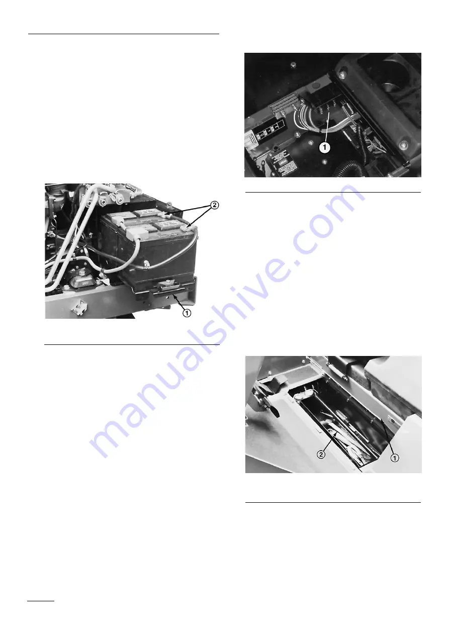
BRAKE SYSTEM SERVICE

Check the brake fluid level every 50 hours operation.
Replace fluid every 1000 hours operation, or yearly.
Replenish the system with DOT 3 hydraulic brake fluid. To
check the fluid level:

1.

Raise the floor panel in the front of the seat 
(Fig. 53). Remove the tool tray.

Figure 53

1.

Floor plate 

2.

Tool tray

2.

Snap the cover bail off the cover and remove the
cover from the master cylinder (Fig. 54).

Maintenance

38

Summary of Contents for GROUNDSMASTER 580-D 30581

Page 1: ...EL NO 30581 80001 UP GROUNDSMASTER 580 D The TORO Company 1999 To understand this product and for safety and optimum performance read this manual before starting operation Pay special attention to SAF...

Page 2: ...pages 3 5 IMPORTANT highlights special mechanical information and NOTE emphasizes general product information worthy of special attention Whenever you have questions or need service contact your local...

Page 3: ...d and remove all objects which may be thrown by the machine 3 WARNING Petrol is highly flammable Store fuel in containers specifically designed for this purpose Refuel outdoors only and do not smoke w...

Page 4: ...before clearing blockages before checking cleaning or working on the lawn mower after striking a foreign object Inspect the lawn mower for damage and make repairs before restarting and operating the...

Page 5: ...5 m s2 at the posterior based on measurements of identical machines per ISO 5349 procedures This unit does not exceed a vibration level of 0 5 m s2 at the posterior based on measurements of identical...

Page 6: ...ion Dismember ment front engine mowerin rearward motion Severing of fingers or hand engine fan Whole body entanglement implement input drive line Fingers or hand entangle ment chain drive Hand arm ent...

Page 7: ...e polarity Minus decrease negative polarity Horn Battery charging condition Hourmeter elapsed operating hours Fast Slow Continuous variable linear Volume empty Volume full Machine travel direction for...

Page 8: ...oil failure malfunction Fuel level Parking brake Fuel Fuel filter Fuel system failure malfunction Lock Unlock Differential lock 4 Wheel drive Power Take Off Diesel fuel Unleaded fuel Headlights Cutti...

Page 9: ...apered roller bearings in cast iron housings greaseable from the top Self tensioning permanently lubricated belt idlers Castor Wheels Two 10 50 x 3 50 and two 12 x 5 00 heavy duty pneumatic castor whe...

Page 10: ...Leaf Mulcher Cold Start Kit Foam Filled Castor Tires Extra Traction Drive TireSpecifications and design subject to change without notice Specifications 10...

Page 11: ...l Figure 2 1 Battery tray 2 Tray mounting holes 3 Negative connections 4 Positive connections 5 Battery tray mounting screws CHECK ENGINE OIL DAILY The engine is shipped with 10L of oil in the crankca...

Page 12: ...of water and permanent ethylene glycol anti freeze Check the coolant level at the beginning of each day before starting the engine Capacity of the cooling system is 14 7 L 1 Unlatch raise and prop the...

Page 13: ...a rear When turf is dry and harder than normal use higher tire pressure 124 kPa front and rear IMPORTANT Do not operate in HIGH RANGE for extended periods when tire pressure is less than 18 psi becaus...

Page 14: ...within 9 5 mm of one another If they are not determine which cutting unit height can be changed to compensate for difference and either transfer washers from bottom to top to lower unit or from top to...

Page 15: ...initial set up or if height of cut is changed deck skids should also be adjusted Adjust skids by loosening the flange lock nuts Fig 11 positioning the skid at the specified height see chart and re tig...

Page 16: ...e batteries is indicated by a warning indicator light and audible signal Fuel System Warning Fig 13 A warning indicator light and audible signal warn of water in the fuel and need for service Coolant...

Page 17: ...ol is engaged Tilt Steering Control Fig 15 A lever on the right side of the steering column Pivot the lever rearward to release and move the steering column and tower to the desired angle Pivot the le...

Page 18: ...ide Switch Fig 16 17 If the engine has overheated and been shut down by the safety switch depressing the button will allow engine operation Use the button only for emergencies and only at short interv...

Page 19: ...ates fully enclosed multiple disc front brakes Note There is dynamic braking through the closed loop hydrostatic traction drive system Storage Fig 20 A large removable tool storage tray is located und...

Page 20: ...or more than 10 seconds at a time or premature starter failure may result If the engine fails to start after 10 seconds turn the key to the OFF position Recheck controls and procedures wait 10 additio...

Page 21: ...g 25 Operate the priming pump until a solid stream of fuel flows from the vent hole Fig 25 then tighten the air vent plug 6 Push the priming pump down to compress the spring then turn it clockwise to...

Page 22: ...oids or relays for the requested machine function For the electronic controller to control the machine as desired each of the input switches output solenoids and relays must be connected and functioni...

Page 23: ...he engine and raise and lower each cutting unit Note the appropriate LED on the Diagnostic ACE i e LED is illuminated when the cutting unit is lowered and the LED is not illuminated when the cutting u...

Page 24: ...not respond to ignition key inputs The above indicates an ECU problem contact your local authorized TORO distributor for assistance If each output switch is in the correct position and functioning co...

Page 25: ...speed Practice using the cruise control Lower and raise the cutting units individually and simultaneously When thoroughly familiar with machine functions practice operating around trees and obstacles...

Page 26: ...l if used move the PTO switch to DISENGAGE and release it the switch returns to neutral then fully raise the cutting units High Range Ground Speed Operation Toro recommends HIGH RANGE ground speed ope...

Page 27: ...Every 50 hours 8 Hydraulic Cylinder Pivot Bushings 4 Every 50 hours 9 Lift Arm Ball Joints 2 Every 50 hours Outboard Cutting Unit Lift Assemblies 10 Lift Arm Pivots 4 Every 50 hours 11 Anti sway Arm B...

Page 28: ...Maintenance 28 Figure 31 Figure 31...

Page 29: ...the engine oil level after every five hours of operation 1 Unlatch and raise the hood and prop it open Unlatch and remove the left side panel Fig 32 Make sure the hood prop is secured in one of the m...

Page 30: ...tions Replace Hydraulic Filter Torque Head and Adjust Valves Check Engine RPM idle and full throttle Service Air Filter Replace Fuel Water Separator Filter Torque Wheel Lug Nuts Change Engine Oil and...

Page 31: ...is secured in one of the mounting brackets on the hood Unlatch and remove both side panels Fig 32 2 Place the drain pan in line with the drain plug Fig 35 Clean the area around the drain plug Figure 3...

Page 32: ...ing system holds approximately 14 7 L of a 50 50 solution of ethylene glycol anti freeze and water To properly maintain the system use the following procedures 1 Check coolant level each day before st...

Page 33: ...per tension will allow 13mm deflection when a force of 14 Nm is applied on the belt midway between the pulleys If deflection is incorrect proceed to step c If deflection is correct install the panel a...

Page 34: ...ment to air dry Do not use a light bulb to dry the filter element because damage could result Compressed Air Method A Blow compressed air from the inside to the outside of the dry filter element Do no...

Page 35: ...e filter Fig 46 Figure 46 1 Hydraulic Oil Filter 2 Coat the O ring of the replacement filter with clean hydraulic oil before installing 3 To tighten the filter hand turn the filter element onto the fi...

Page 36: ...ig 47 2 Inspect the O rings on the plugs and replace if damaged Install the drain plugs 3 With the machine on level surface fill the reservoir with hydraulic oil until the oil level is midway up in th...

Page 37: ...quality SAE 80 90 weight gear lube to bring the level up to the bottom of the hole and install the plug 5 Repeat steps 1 4 on the opposite gear assembly BATTERY SERVICE IMPORTANT Before welding on th...

Page 38: ...REAKER One 5 amp two 15 amp fuses and a fusible link are incorporated for the protection of the entire wiring circuit The link can be replaced if the total loss of electrical function results They are...

Page 39: ...HIGH RANGE for extended periods when tire pressure is less than 138 kPa because tires may be damaged When tire pressure exceeds 138 kPa HIGH RANGE may be used CUTTING UNIT LUBRICATION Follow guideline...

Page 40: ...itch 5 Fit the deck tilt link over the weldment on the right side of the traction unit and secure with a klik pin Position a link so it clears when the cutting unit is raised Keep the remaining klik p...

Page 41: ...ey could be dangerous 1 Raise cutting unit to transport position engage parking brake shut the engine off and remove key from ignition 2 Using a rag or thickly padded glove grasp end of blade Remove b...

Page 42: ...Front Cutting Unit Note Belts for wing unit spindles are tensioned by spring loaded idlers and normally do not require tensioning 1 Position the machine on level surface lower the cutting unit to the...

Page 43: ...ion spring on the idler assembly is relaxed Fig 64 3 Remove the idler pulley belt retainer 4 Remove the flange head screws securing the gearbox plate and separate the plate and drive motor assembly fr...

Page 44: ...sion on all belts Fig 65 3 Remove the flange head screws securing the gearbox plate to the deck To separate the plate and drive motor assembly from the deck rotate the plate end toward the traction un...

Page 45: ...not fit recommended standards add shims between the cutting deck and spindle housing proceed to step 6 If the measurements meet standards proceed to step 5 5 Rotate the blades so the tips lineup with...

Page 46: ...e could result in personal injury from machine movement 4 With the engine OFF loosen the nut on the carriage bolt and allow the bearing to locate the cam Fig 70 Carefully tighten the nut on the carria...

Page 47: ...against traction pedal then loosen nut until next slot aligns with hole in ball joint and install cotter pin CYLINDER HEAD BOLTS Re torque initially after 50 operating hours and check every 1000 oper...

Page 48: ......

Reviews: