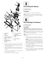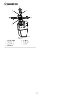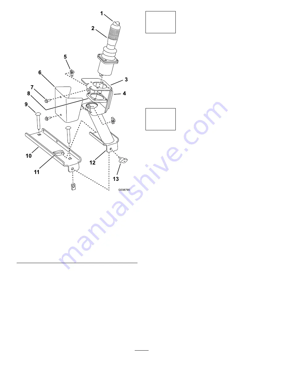
Figure 4
1.
Toggle switch
8.
Joystick-mounting plate
2.
Joystick
9.
Carriage bolts
3.
Joystick pod
10.
Joystick pod mounting
bracket
4.
Decal here (apply on the
side of the joystick pod)
11.
Tab
5.
Clip (2)
12.
Joystick pod base
6.
Joystick pod cover
13.
Knob
7.
Hex-head screws (1/4 x
5/8 inch)
2.
Slide the bottom bracket of the joystick assembly along
the bracket until it stops under the tab on the joystick
pod mounting bracket.
3.
Insert the thumbscrew through the hole in the front of
the bottom bracket of the joystick and tighten it firmly
by hand.
4.
Connect the wire end on the joystick to the appropriate
connector on the wire harness.
5.
Apply the decal to the joystick pod (
5
Connecting the Battery
No Parts Required
Procedure
Connect the negative (–) battery cable to the battery.
Note:
When the kit is properly installed, the power point
and fuse block should have power only when the ignition
switch is in the O
N
position.
6
Downloading the Software
No Parts Required
Procedure
Important:
This step must be performed by a Toro
Commercial Products Distributor Service staff person.
Note:
You will need a laptop PC (with the current version
of Toro Diag software loaded onto it) and a communication
cable for USB to CAN for Toro Diag.
Note:
Verify that the software revision is at the current
release level.
1.
Download the current version of Toro Diag software
available from the Toro Distributor Portal website.
Note:
If the machine has not yet been converted to
the Toro Diag, locate the loop-back connector on the
main machine wire harness (located near the main
machine controller), and remove it. Replace this plug
with the cap without the loop wire as indicated in the
Toro Diag service bulletin.
2.
Plug the CAN communication cable into the CAN
communications port located near the main controller
on the main wire harness.
3.
Follow the instructions on the screen for programming
and/or re-programming the software on the accessory
controller and the main machine.
5
Summary of Contents for Groundsmaster 360
Page 8: ......


