background image

When the control dial is turned to the 

OFF

position, the

controller immediately shuts off any watering operation
currently in progress. Leaving the control dial in the

OFF

position will prevent all automatic and manual

watering operations. The controller will continue to track
the current time and day of the week.

For extended shutdown of the sprinkler system leave the
control dial in the 

OFF

position.

The word OFF will be displayed 
for 8 minutes. The automatic sta-
tus display will then appear. 

Automatic operation is resumed
by turning the control dial to the

RUN

position.

This feature enables all watering operations to be
delayed from 1 to 7 days. For example, rain is forecast in
your area for the next two days. Instead of turning the
controller off (and possibly forgetting to turn it back on), a
rain delay of 3 days can be easily entered. At the end of
3 days, the controller will resume automatic operation as
scheduled.

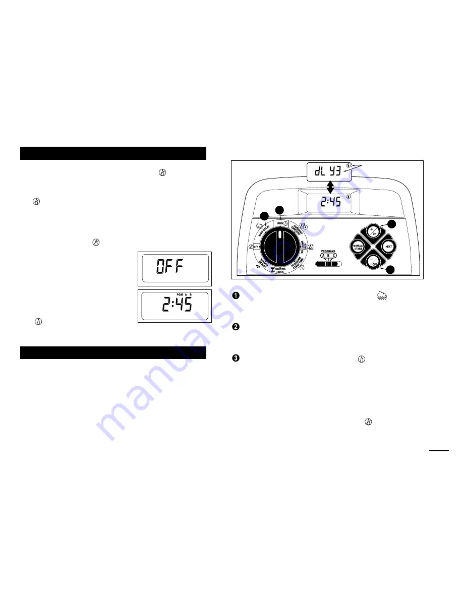
Turn the control dial to the

RAIN DELAY

position.

The rain delay display will begin alternating with the
automatic status display.

To set the number of rain delay days, press the 

+/

ON

or 

–/

OFF

button until the desired number (1–7) is

flashing.

Return the control dial to the

RUN

position.

Note: The rain delay number will automatically
decrease as each day passes. When the number
reaches 0 (zero), automatic operation will resume at
the next scheduled start time.

To cancel the rain delay, turn the control dial
momentarily (3 seconds) to the 

OFF

position.

Using the Rain Delay Feature

Turning Off the GreenKeeper 212

33

2

2

1

3

PM

  MO   

PM

  MO   

Flashing

Summary of Contents for GreenKeeper 212

Page 1: ...endar Interval and Odd Even Days 1 Min to 4 Hrs Station Run Time 4 Start Times Per Program Battery Back Up Automatic Pump Start Seasonal Run Time Adjust Rain Delay Rain Sensor Ready Remote Control Ready Snap in Wire Connectors Automatic Sprinkler System Controller User s Guide MANUAL START ON NEXT OFF PROGRAMS B C A R R ...

Page 2: ... 19 Setting Program Start Times 20 Setting Station Run Times 21 Controller Installation Indoor Model Installation 22 Connecting the Valves 23 Connecting a Pump Start Relay 24 Connecting the Transformer 24 Outdoor Model Installation 25 Preparing the Cabinet for Installation 25 Installing the Cabinet 26 Connecting the Valves 27 Connecting a Pump Start Relay 28 Connecting the Power Source 28 29 Conne...

Page 3: ...Controller Components GreenKeeper 212 Introduction and Set Up 2 1 3 BATTERY 2 ...

Page 4: ...tion numbers J Percent symbol Indicates the Season Adjust feature is in use K Day of the week identifiers L Run Time symbol Hourglass is displayed when setting the watering station run times 2 Control Buttons ON button Increases the time display scrolls for ward through the program information and selects watering days OFF button Decreases the time display scrolls backward through the program info...

Page 5: ...h Controls the sensor input circuit Switch positions provided for sensor circuit On and Off 11 Sensor Connection Terminals Snap in connec tors for connection of an optional Toro Rain Switch 12 Valve Common Connection Terminal Snap in wire connector for the valve common wire 13 Pump Master Valve Connection Terminal Snap in wire connector for a pump start relay or master valve 14 Transformer Connect...

Page 6: ...5 BATTERY MANUAL START ON NEXT OFF PROGRAMS B C A 16 18 19 20 BATTERY 16 17 18 5 6 7 10 11 12 13 14 9 8 15 3 4 Controller Components ...

Page 7: ...within the controller identifying it as Station 1 Station 2 etc The controller operates the valves in order one at a time In other words one station would water completely before another station would turn on This is called a watering cycle The information stored in the controller memory which determines when and how long the sta tions will water is called a program The next section of this guide ...

Page 8: ...troller skips station 3 and turns on station 4 which runs for 20 minutes and shuts off Station 5 is skipped and the watering cycle ends at 5 40 AM As you can see from this example only one program start time was needed to operate three different stations Because of variations in plant watering needs the GreenKeeper 212 provides three separate programs The programs called A B and C are completely i...

Page 9: ...ering every sev enth day Once you have selected an Interval schedule you can choose which day of the week will be the first day of the Interval The number of days in the Interval deter mines the available start days For example if you have selected a 3 day Interval and today is Sunday you may choose to start the Interval today Monday or Tuesday This illustration shows how an Interval schedule woul...

Page 10: ... time is displayed In this example program A has one start time start time number 1 set for 5 00 AM Setting the Station Run Time A station run time is the length of time the station con trolled by the valve will water during the program water ing cycle The run time for each station can be set from Off no run time to 4 hours in one minute increments A station is assigned to a program when it is giv...

Page 11: ...pencil so changes can be easily made After installing the indoor model controller remove the form and store it in the pocket formed between the mounting bracket and the back of the con troller housing Refer to the example form shown on the opposite page and fill out your form in a similar manner with the follow ing information Location Identify the location of each watering sta tion and the type o...

Page 12: ...11 Example ...

Page 13: ... 6 7 8 9 10 11 12 2 3 4 5 6 7 1 2 3 4 5 6 7 1 2 3 4 5 6 7 CALENDAR LOCATION ZONE STATION RUN TIME STATION RUN TIME STATION RUN TIME WATERING DAY SCHEDULE INTERVAL ODD ODD EVEN EVEN PROGRAM START TIMES 1 2 3 4 PROGRAM A Watering Schedule Form PROGRAM B PROGRAM C ODD EVEN ODD EVEN ...

Page 14: ...tery into the cabinet compart ment as shown in Figure 1 2 The display will begin flashing 12 00 AM Press the ON button to stop the display from flashing The colon will continuously flash while displaying the time and during watering operation The Power Off symbol will be displayed until the main power supply is connected 3 Locate the battery charger switch 9 as indicated in Figure 2 If an Alkaline...

Page 15: ...tering sched ule within its memory to assist you in two ways First it will restore watering operation in case your watering pro gram is lost due to a power interruption lasting longer than the battery backup reserve This prevents your landscape from going unwatered if the power outage occurs while you are away Secondly if you do not want to program your GreenKeeper 212 you can use the permanent wa...

Page 16: ...rements are quite different than the permanent values Note When power is first applied the GreenKeeper 212 will always reset to the permanent program values To Reset the Permanent Program Figure 4 Turn the control dial to the OFF position OFF will be displayed Press the ON and OFF buttons at the same time until CLR is displayed Return the control dial to the RUN position To Clear the Memory Figure...

Page 17: ...step 5 Refer to Example 1 To set the current day press the ON button to scroll forward or the OFF button to scroll backward until the current weekday is displayed The weekday abbreviations are as follows SU Sunday MO Monday TU Tuesday WE Wednesday TH Thursday FR Friday SA Saturday When the current time and day are displayed return the control dial to the RUN position To adjust the display press th...

Page 18: ...flashing To select Sunday as a watering day press the ON button To remove Sunday from the schedule press the OFF button MO Monday will now begin flash ing Continue to select or remove each day of the week until only the desired watering days are shown 6 To set a Calendar schedule for another program repeat all of the steps beginning at step When you have completed setting the Calendar schedule for...

Page 19: ...day of the week on which the Interval will start will be shown To change the Interval number press the ON or OFF button until the desired number is flashing Press the NEXT button The Interval start day will begin flashing To change the Interval start day press the ON button or the OFF button until the desired day is flashing 8 To set an Interval schedule for another program repeat all of the steps...

Page 20: ...o set an Odd or Even schedule for another program repeat steps and as needed When you have completed setting the Odd or Even schedule for each program as needed return the control dial to the RUN position Turning Off a Program Note Turning off a program does not alter or erase a preset watering day schedule Selecting Off simply places the program on hold until one of the watering day schedules is ...

Page 21: ... Note To remove the start time select OFF by pressing the ON and OFF buttons at the same time and continue at step To set the hour and AM PM press the ON or the OFF button until the desired hour is flashing Press the NEXT button The minute digits will begin flashing To set the minutes press the ON or OFF button until the desired minute is flashing Press the NEXT button The next program start time ...

Page 22: ...time or OFF will begin flashing To set the run time press the ON or OFF button until the desired run time is shown Note To remove the run time select OFF by press ing the ON and OFF buttons at the same time Press the NEXT button The next station number will begin flashing 7 Repeat steps and as needed to set change or remove the run time for the remaining stations 8 To set the station run time for ...

Page 23: ...ower edge of the bracket away and downward from the controller housing 3 Place the mounting bracket A against the wall align ing the top edge at about eye level Drive three 1 25mm wood screws B into the wall through the three holes provided in the bracket Note If you are installing the bracket on drywall or masonry install screw anchors C to prevent screws from loosening 4 Optional Insert 3 4 19mm...

Page 24: ...and possible short circuits use a grease cap or similar waterproofing method to insu late each connection 5 Route the wire cable into the controller through the large opening in the base of the housing or through PVC conduit if it is installed Strip insulation back 1 2 13mm from all cable wires Note The GreenKeeper 212 has snap in wire termi nals To attach wires simply raise the lever insert the s...

Page 25: ...terminal with a valve connected Note For model GK212 26 04 contact your Toro dis tributor for the recommended transformer CAUTION Do not plug the transformer into an electrical outlet until all of the wiring procedures have been completed 1 Route the cable from the transformer 17 through the small opening provided in the base of the housing Wrap the cable around the post as shown below 2 Connect o...

Page 26: ... a 3 16 5mm drill bit Four wiring access holes are provided in the cabinet base as follows D 1 2 13mm for power and equipment ground wires E 1 2 13mm plugged for optional Toro Rain Switch wires F 3 4 19mm for sprinkler valve wires G 1 2 13mm plugged for optional Toro remote control cable 4 If planning to install the optional Toro components remove the plugs as necessary Outdoor Model Installation ...

Page 27: ...ou are installing the controller on drywall or masonry install screw anchors to prevent screws from loosening Use the dimension shown to predrill holes for screw anchors 3 Hang the cabinet on the screw using the keyhole slot B on the back panel Make sure the cabinet slides down securely on the screw 4 Install the lower mounting screw s and tighten securely Note Conduit and adapters are not provide...

Page 28: ...ist on wire connectors To prevent corrosion and possible short circuits use a grease cap or similar waterproofing method to insu late each connection 5 Strip back 1 2 13mm of insulation from all cable wires at the other end of the valve connection cable Note The GreenKeeper 212 has snap in wire termi nals To attach wires simply raise the lever insert the stripped wire and press the lever down to s...

Page 29: ...rtment Note The controller terminal block accepts wire size up to 12 AWG 4mm2 2 Remove 3 8 10mm insulation from the wire ends 3 Using a small flat blade screwdriver secure the wires as shown to the terminal block as follows Line or Line 1 L1 to L Neutral or Line 2 L2 to N and Equipment Ground to 4 Install and secure the transformer compartment cover 5 Apply power to the controller Connecting the P...

Page 30: ...ammed 1 Route the wire cable from the Toro Rain Switch into the con troller housing through the access hole provid ed 2 The Rain Switch cable has four wires two cop per wires and two silver wires Connect the heavier 18 AWG 1 0mm2 copper wire and the thinner 24 AWG 0 50mm2 silver wire to the terminals labeled SENSOR 11 Trim off the remaining two wires 3 Set Sensor Switch 10 as required ON allows th...

Page 31: ...matic operation will occur whenever a programmed watering day and start time match the current time and day The Automatic mode is selected when the control dial is in the RUN position While in the automatic mode the display will show two types of information status and operation This illustration shows the status display In this example the current time is 2 45 PM and the current day is Monday Pro...

Page 32: ...MS switch to select the program you wish to start Choose one of the following manual operations To operate the selected program with all assigned stations press the MANUAL START button two times to begin watering To operate only selected stations press the MANUAL START button then press the ON button to select the flashing zone number or press the OFF button to skip the zone number Continue select...

Page 33: ...Press the ON and OFF buttons at the same time two times All watering operations will be canceled and the con troller will return to the automatic mode Note Placing the control dial in the OFF position for two seconds then back to RUN will also cancel all watering operations To Skip Stations Press the NEXT button one time The station currently watering will shut off and the next station will start ...

Page 34: ...ast in your area for the next two days Instead of turning the controller off and possibly forgetting to turn it back on a rain delay of 3 days can be easily entered At the end of 3 days the controller will resume automatic operation as scheduled Turn the control dial to the RAIN DELAY position The rain delay display will begin alternating with the automatic status display To set the number of rain...

Page 35: ...oling or running off For example adjusting to 150 would first increase a 20 minute sta tion run time to 30 minutes then split the time in half and run two watering cycles back to back with 15 minutes in each operation During operation the symbol will flash to indicate a multiple watering operation Note All station run times are retained in the controller memory and returned to their set value when...

Page 36: ...1 Turn the control dial to the OFF position 2 Remove the lower front cover from the controller housing by sliding it downward 3 Place the back of the station control module model number MOD 212 02 squarely between the guides of the first open expansion slot from left to right Pushing lightly on the bottom of the module slide it upward until it locks into position 4 To connect the valve wires refer...

Page 37: ...rt time on the program Season Adjust setting greater than 100 Remedy Replace the battery and one or more of the following Replace the fuse See page 35 Check the transformer connections indoor model or circuit breaker ser vice panel outdoor model Shorten station run times and or space start times farther apart Check the wire connections at the control valve and controller Enter a station run time S...

Page 38: ...uivalent Input 120 V a c 60 Hz 0 5A Output 24 V a c 60 Hz 20 30 VA Power Specifications continued Outdoor Model Export Built in Transformer TUV Approved SAA Approved Input 230 240 V a c 50 60 Hz 0 1A Output 24 V a c 50 60 Hz 20 VA Outdoor Model Australia Built in Transformer SAA Approved Input 230 240 V a c 50 60 Hz 0 1A Output 24 V a c 50 60 Hz 20 VA Maximum Load Per Station 0 30 Amps 24 V a c Ma...

Page 39: ...r s recommended specifications Product failures due to acts of God i e lightning flooding etc are not covered by this warranty Neither Toro nor Toro Warranty Company is liable for failure of products not manufactured by them even though such products may be sold or used in conjunc tion with Toro products During such warranty period we will repair or replace at our option any part found to be defec...

Reviews: