


Pressure Sensor Installation
The GDC controller is designed to accept both normally-open and normally-closed pressure
sensor. Set the pressure sensor model in GDC controller preference menu.
Step 1 – Place the controller’s power switch to OFF.
Step 2 – Route the pressure sensor’s cable into the controller.
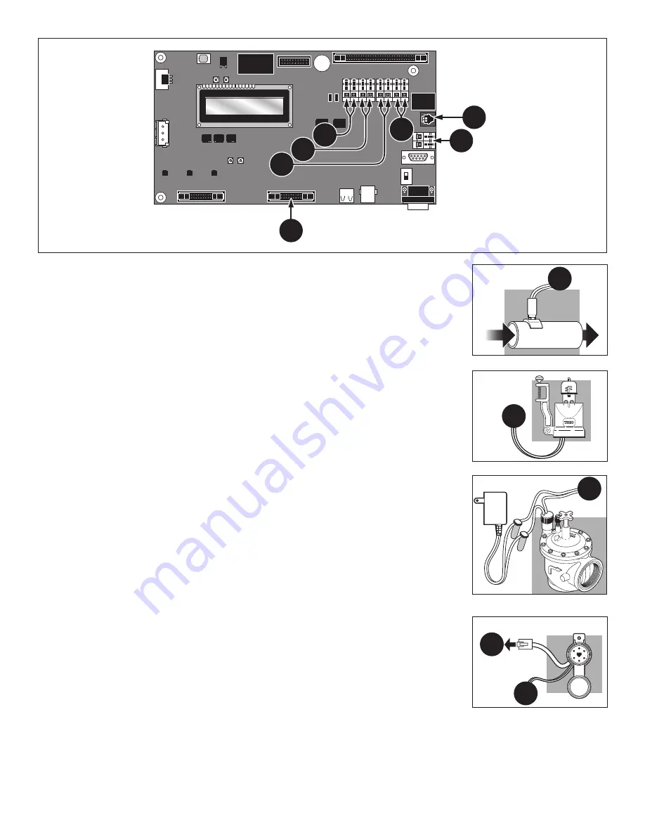
Step 3 – Connect the cable wires to the Pressure Sensor Terminals labeled A in Figure 6.
Step 4 – Place the controller’s switch to ON.
Rain Sensor Installation
The GDC controller is designed to accept both normally-open and normally-closed rain switch.
Set the rain switch model in GDC controller preference menu.
Step 1 – Place the controller’s power switch to OFF.
Step 2 – Route the rain sensor’s cable into the controller.
Step 3 – Connect the cable wires to the Rain Sensor Terminals labeled B in Figure 6.
Step 4 – Place the controller’s switch to ON.
Master Valve / Pump Relay Installation
GDC provide switch terminals to control a master valve or a pump relay if the system requires it.
Step 1 – Place the controller’s power switch to OFF.
Step 2 – Connect the Positive/Hot wire of the power source that controls the master valve or
the pump relay to the Master valve/Pump relay switch terminal. See Figure 6, D.
Step 3 – Route another wire from the Master Valve / Pump terminal and connect it to the
master valve solenoid or pump relay.
Step 4 – Connect the Negative/Equipment ground wire of the power source to the master
valve solenoid or pump relay.
Step 5 – Place the controller’s switch to ON.
Toro Maintenance Remote (TMR) Receiver Plug Installation
The GDC controller is fully ccompatible with the TMR remote. See TMR’s User’s Guide for
operating and mounting instructions.
Step 1 – Place the controller’s power switch to OFF.
Step 2 – Route the TMR’s receiver plug cable into the controller.
Step 3 – Connect the RJ45 plug into the socket labeled E in Figure 6.
Step 4 – Connect the power wires into the +24 VDC terminals labeled F in Figure 6.
Step 5 – Place the controller’s switch to ON.
Figure 6
A
B
C
D
E
F
G
D
A
B
E
F
Figure 7
Figure 8
Figure 9
Figure 10


