background image

8

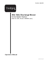
5. Hang the belt over the mower, then thread it forward

through the belt guide (Fig. 12) on the mower.

m–3457

1

2

Figure 12

1.

Belt

2.

Belt guide

6. Loop the other end of the belt over the drive pulley of

the mower. Additional belt slack can be obtained (if
needed) by turning the belt tension adjustment knob
(Fig. 10).

7. Make certain that the wide side of the PTO drive belt is

toward the outside diameter of all (four) pulleys (Fig.
13).

m–4230

ÏÏÏÏÏ

ÏÏÏÏÏ

ÏÏÏÏÏ

2

1

Figure 13

1.

Pulley outside diameter

2.

Wide side of belt

8. Adjust the belt tension.

A. Push the belt tension release arm toward the pulley

box to tension the belt.

B. Check the tension indicators on front of the pulley

box. The two arrow points on the indicators should
line up (Fig. 10).

C. If the tension indicators do not line up, release the

belt tension, turn the adjustment knob and repeat
steps A through C until the indicators line up
(Fig. 10).

D. Swing the tension release arm into the pulley box

and seat it by moving it into the position shown in
Figure 10.

9. Loosen the belt guide bolt (Fig. 14).

m–3465

1

2

3

4

Figure 14

1.

Belt guide

2.

Belt

3.

Belt touches here

4.

Belt guide bolt

10. Adjust the belt guide so that it just touches the belt on

the inside arm of the guide (toward the center of the
mower) (Fig. 14).

11. Tighten the belt guide bolt.

12. Replace the front grill of the tractor.

Adjusting the Mower

Adjusting the Height of Cut

You can adjust the rear support wheels in different hole
locations for 1-1/2 to 4-1/2 in. (4 to 11 cm) heights of cut.

1. Start the tractor, set the parking brake, and raise the

mower. Get off the tractor.

2. Pull the height-of-cut lever out to disengage it from the

quadrant (Fig. 15).

Summary of Contents for 78449

Page 1: ...Operator s Manual Original Instructions GB Form No 3326 570 48in Side Discharge Mower for 5xi Garden Tractors Model No 78449 Serial No 230000001 and Up...

Page 2: ...ver you need service genuine Toro parts or additional information contact an Authorized Service Dealer or Toro Customer Service and have the model and serial numbers of your product ready Figure 1 ill...

Page 3: ...s Safety decals and instructions are easily visible to the operator and are located near any area of potential danger Replace any decal that is damaged or lost 93 7316 1 Thrown object hazard stay a sa...

Page 4: ...in the spring slides over the stud on the mower housing 4 Slide the rubber bushing and nylon washer over the stud at the front of the mower 5 Place the discharge chute over the stud and secure it wit...

Page 5: ...p the engine and remove the ignition key 3 If you have previously had a snowthrower blade or tiller attached to the attachment lift remove the two clevis pins on each side of the attachment lift Fig 4...

Page 6: ...1 2 Figure 7 Left Side of Tractor Shown 1 J pin 2 Mower slot in side mounting bracket 7 On the left side pull out the attachment lift J pin and slide it into the slot on the other mower mounting brac...

Page 7: ...u may be burned Allow the tractor to cool before performing maintenance or touching components under the hood Caution 2 Release the belt tension release arm on the pulley box housing and swing it out...

Page 8: ...C If the tension indicators do not line up release the belt tension turn the adjustment knob and repeat steps A through C until the indicators line up Fig 10 D Swing the tension release arm into the p...

Page 9: ...tion Ensure that the two adjustable front wheels are off of the ground 1 Disengage the PTO set the parking brake lower the attachment lift stop the engine and remove the ignition key 2 Carefully rotat...

Page 10: ...Side of Tractor Shown 1 Indicator 2 Adjustment cam 3 Lift arm 4 Pivot point 5 Lowers front of deck 6 Raises front of deck 2 If they are not park the machine on a level surface set the parking brake lo...

Page 11: ...ff the tractor Place the mower height of cut lever in the lowest cut position 3 Lower the mower until its weight is completely on its wheels not on the tractor 4 Stop the engine and remove the ignitio...

Page 12: ...mple clearance to slide out the mower 13 Stop the engine and remove the ignition key 14 Slide the mower out from the right side of the tractor Operation Danger Without the grass deflector discharge co...

Page 13: ...in 9 5 mm off the ground 2 To adjust the wheel height remove the hairpin cotter and pin to change hole location Fig 25 3 Select a hole position so the wheel is approximately 3 8 in 9 5 mm off the gro...

Page 14: ...s evenly Use the washout port to clean clippings and dirt from the underside of the mower after each use If grass and dirt build up inside the mower cutting quality will eventually become unsatisfacto...

Page 15: ...des Important There are two different sizes of blades The shorter blade goes into the center spindle The two longer blades go on the outside spindles Fig 31 1 Hold the blade end using a rag or thickly...

Page 16: ...every 25 operating hours or once a year whichever occurs first Grease more frequently when operating conditions are extremely dusty or sandy Grease Type General purpose grease How to Grease 1 Disengag...

Page 17: ...or bagging Replacing the Blade Drive Belt Removing the Blade Drive Belt 1 Remove the mower refer to Removing the Mower page 11 2 Remove the pulley cover mounting screws and pulley covers from the bla...

Page 18: ...death Replace a broken or missing washout fitting immediately before using the mower again Plug any hole s in the mower with bolts and locknuts Never put your hands or feet under the mower or through...

Page 19: ...ler Blades do not rotate 1 The blade drive belt is worn loose or broken 1 Install a new blade drive belt 2 The blade drive belt is off the pulley 2 Install the blade drive belt and check idler pulley...

Page 20: ...ne is not at full throttle 7 Always operate engine powered attachments at full throttle 8 The PTO is being engaged when the mower is in tall uncut grass or weeds 8 Engage the PTO only in shorter or pr...

Reviews: