background image

Setup

Loose Parts

Use the chart below to verify that all parts have been shipped.

Step

Description

Qty.

Use

Handle bolts

4

Curved washers

4

1.

Locknuts

4

Install the upper handle.

2.

No parts required

Install the traction control linkage.

Carriage bolts

2

3.

Locknuts

2

Install the chute control rod.

4.

No parts required

Fill the engine with oil.

5.

No parts required

Check the tire pressure.

6.

No parts required

Check the skids and scraper.

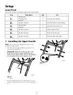
1. Installing the Upper Handle

Note:

Do not remove the rubber band until you have

installed the upper handle.

1. Lift and rotate the upper handle and position it over

the lower handle (Figure 3).

Important:

Route the cables attached to the

Quick Stick inside the upper handle legs and
ensure that the cables and the wire for the headlight
are not pinched between the handle sections.

Figure 3

1. Cables

2. Secure the upper handle with 4 handle bolts, 4 curved

washers, and 4 locknuts from the loose parts bag (Figure
4).

Figure 4

6

Summary of Contents for 38621

Page 1: ...ure 1 identi es the location of the model and serial numbers on the product Write the numbers in the space provided Figure 1 1 Model and serial number location Model No Serial No This manual identi es...

Page 2: ...Know how to stop the unit and disengage the controls quickly Never allow children to operate the equipment Never allow adults to operate the equipment without proper instruction Keep the area of oper...

Page 3: ...ufacturer of snow thrower such as wheel weights counterweights cabs etc Never operate the snow thrower without good visibility or light Always be sure of your footing and keep a rm hold on the handles...

Page 4: ...r s ear of 92 dBA based on measurements of identical machines per EN 11201 Sound Power This unit has a guaranteed sound power level of 108 dBA based on measurements of identical machines per EN 3744 V...

Page 5: ...wer 2 Warning read the Operator s Manual 4 Cutting dismemberment hazard impeller keep away from moving parts remove the ignition key and read the instructions before servicing or performing maintenanc...

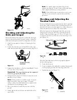
Page 6: ...pressure 6 No parts required Check the skids and scraper 1 Installing the Upper Handle Note Do not remove the rubber band until you have installed the upper handle 1 Lift and rotate the upper handle a...

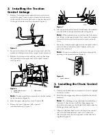
Page 7: ...runnion into the hole in the speed selector lever Figure 6 Note If the trunnion does not t into the hole when you lift up on the speed control rod rotate the trunnion upward or downward on the speed c...

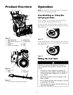
Page 8: ...omes with 26 oz of oil in the engine Note Before starting the engine check the oil level and add oil if necessary Max ll 26 oz 0 77 l type automotive detergent oil with an API service classi cation of...

Page 9: ...e engaged or disengaged freewheeling To freewheel slide the wheels inward and insert the axle pins through the outer axle holes but not through the wheel hubs Figure 16 Figure 16 To self propel slide...

Page 10: ...20 Figure 20 3 Rotate the fuel shutoff valve counterclockwise to open it Figure 21 Figure 21 4 Rotate the choke to the On position Figure 22 Figure 22 5 Insert the ignition key Figure 23 Figure 23 6 F...

Page 11: ...Close the fuel shutoff valve by rotating it clockwise Figure 26 Figure 26 4 Pull the recoil starter 3 or 4 times This helps prevent the recoil starter from freezing up Operating the Traction Drive Im...

Page 12: ...necessary Otherwise take the snowthrower to an Authorized Dealer for service If the auger and impeller continue to rotate when you release the auger impeller lever you could seriously injure yourself...

Page 13: ...to clear any remaining snow from inside the housing Rotate the Quick Stick to prevent it from freezing Stop the engine wait for all moving parts to stop and remove all ice and snow from the snowthrowe...

Page 14: ...i 116 137 kPa Drain the gasoline and run the engine to dry out the fuel tank and the carburetor at the end of the season Have an Authorized Service Dealer inspect and replace the traction drive belt a...

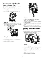
Page 15: ...e nuts that secure both skids to the auger sides Note To quickly adjust the skids if they loosen support the scraper 1 8 inch 3 mm off the pavement then adjust the skids down to the pavement Note If t...

Page 16: ...usts the tension on the cable Figure 40 7 Adjust the turnbuckle until you obtain the proper gap 8 Tighten the jam nut 9 Insert the 2 screws you previously removed on the belt cover 10 If the auger imp...

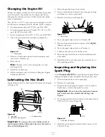
Page 17: ...r wheel or the aluminum friction drive plate because the traction drive will slip Figure 43 1 Drain the gasoline from the fuel tank 2 Tip the snowthrower forward onto its auger housing and block it so...

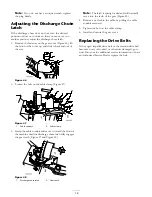
Page 18: ...asp the cable conduit and move it toward the front of the machine until the discharge chute latch fully engages the gear teeth Figure 47 and Figure 48 Figure 48 1 Discharge chute latch 2 Gear teeth No...

Page 19: ...run until it stops When you can no longer start the engine it is suf ciently dry 9 Stop the engine and allow it to cool 10 Remove the ignition key 11 Disconnect the spark plug wire 12 Remove the spar...

Page 20: ...ve is not open 3 Open the fuel shutoff valve 4 The throttle is not in the Fast position 4 Move the throttle to the Fast position 5 The fuel tank is empty or the fuel system contains stale fuel 5 Drain...

Page 21: ...er into a lower gear 3 You are trying to remove too much snow per swath 3 Reduce the amount of snow removed per swath 4 You are trying to remove extremely heavy or wet snow 4 Don t overload the snowth...

Page 22: ......

Page 23: ...A Italy 39 0331 853611 Irriamc Portugal 351 21 238 8260 Jean Heybroek b v Netherlands 31 30 639 4611 Lely U K Limited United Kingdom 44 1480 226 800 Maquiver S A Columbia 57 1 236 4079 Maruyama Mfg Co...

Page 24: ...the product If for any reason it is impossible for you to contact your seller you may contact any Toro Authorized Distributor to arrange service 2 Bring the product and your proof of purchase sales r...

Reviews: