
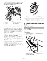

2. Move the speed selector lever (Figure 13) on the
control panel to the R (Reverse) position.
3. Install the speed selector rod into the speed selector
arm, add a flat washer on the selector rod, and secure
it with a cotter pin (Figure 6).
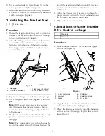
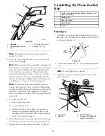
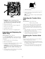
3. Installing the Traction Rod
1
Flange locknut
Procedure
1. Thread the flange locknut (flange side up) onto the
bottom of the traction control rod, below the loop
in the lower traction rod (Figure 4).
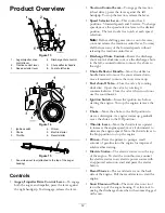
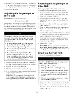
2. Adjust the 2 flange nuts up or down on the traction
rod until the distance between the top of the
handgrip and the bottom of the traction control
lever is approximately 4-1/2 inches (11.4 cm) as
shown in Figure 7.
Figure 7
1.
Handgrip
3.
1 to 2 inches (3 to 5 cm)
2.
Traction control lever
4.
4-1/2 inches (11.4 cm)
3. Tighten the 2 flange nuts until they are finger tight.
4. Move the speed selector lever (Figure 13) into third
gear.
Note:
If the speed selector lever does not move
into third gear, adjust the speed selector before
continuing. Refer to Adjusting the Speed Selector
in Maintenance.
5. Slowly pull the snowthrower backward while slowly
pressing the traction control lever toward the
handgrip.
Note:
The adjustment is correct when the wheels
stop rolling backward and the distance between the
top of the handgrip and the bottom of the traction
control lever is 1 to 2 inches (3 to 5 cm) as shown
in Figure 7.
6. Adjust the 2 flange nuts, if necessary, to obtain the
proper distance between the top of the handgrip and
the bottom of the traction control lever.
7. Tighten the flange nuts securely.
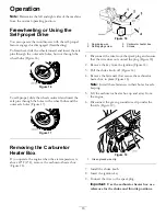
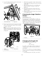
4. Installing the Auger/ Impeller
Drive Control Linkage
1
Clevis pin
1
Cotter pin
Procedure
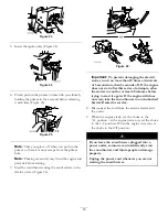
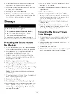
1. Loosen the jam nut above the clevis on the upper
control rod (Figure 8).
Figure 8
1.
Upper control rod
4.
Cotter pin
2.
Jam nut
5.
Lower control rod
3.
Clevis
6.
Clevis pin
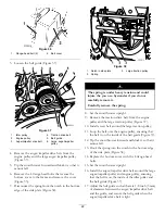
2. Align the holes in the clevis and the lower control
rod and insert the clevis pin (Figure 8).
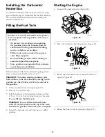
3. Check the distance between the top of the handgrip
and the bottom of the auger/impeller drive control
lever (Figure 9).
9
Summary of Contents for 38605
Page 27: ...Notes 27 ...


