


5.
Secure the headlight wiring harness to the operator's
platform with the harness clips and cable ties.
6.
Install the steering tower cover.
7.
The front and rear cab lights cannot be used for CE
applications. Disable the front and rear cab lights as
follows:
•
Front
-Pop the lights out of the cab roof and
disconnect the wires from the lights. Reinstall the
lights into the cab.
•
Rear
-Remove the screws securing the lenses to
lights. Remove the bulbs from the lights and
reinstall the lenses to the lights.
For Groundsmaster 4100, Models 30604
and 30608
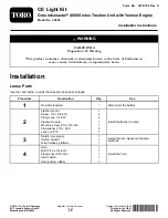
1.
Remove the (2) bolts, washers and nuts from the front
of the operator's platform (Figure 10).
g021734
Figure 10
1.
Bolt, washer and nut (2)
2.
Fasten the R.H and L.H. headlight brackets to the
front of the operator's platform with the bolts, washers
and nuts previously removed. Position the brackets as
shown in Figure 11.
3.
Fasten the R.H and L.H. headlight assemblies to
the headlight brackets (Figure 11) with the fasteners
supplied with the lights. Make sure the turn signal lens
on the headlight is positioned toward the outside of
the machine.
4.
Plug the connector body from the enclosed headlight
wire harness into the harness connector of the steering
tower wire harness under the steering cover opening.
5.
Route the headlight wire harness underneath the front
edge of the operator's platform and connect it to the
headlights (Figure 11).
g021708
2
4
1
5
6
3
Figure 11
1.
Wire harness
4.
Headlight bracket, R.H.
2.
Headlight assembly, R.H.
5.
Headlight assembly, L.H.
3.
Harness clip
6.
Headlight bracket, L.H.
6.
Secure the headlight wiring harness to the headlight
brackets and operator's platform with the harness clips
and cable ties.
7.
Install the steering tower cover.
6
Installing the Light Switch
Parts needed for this procedure:
1
Switch, light
Procedure
Note:
The light switch is already installed on models 30602,
30603, 30606 and 30607.
1.
Remove the (2) screws that secure the plate to the right
cover of the control arm (Figure 12).
7
Summary of Contents for 30660
Page 12: ......


