


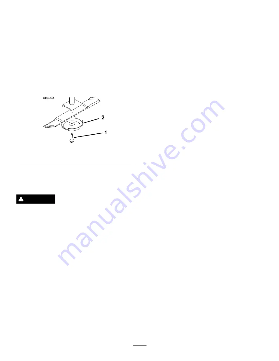
2. Grasp the end of the blade using a rag or thickly
padded glove. Remove the blade bolt, anti-scalp cup,
and blade from the spindle shaft (Figure 86).
3. Install the blade, anti-scalp cup, and blade bolt.
Tighten the blade bolt to 85 to 110 ft-lb (115 to 149
N
⋅
m).
Important:
The curved part of the blade must
be pointing toward the inside of the cutting unit
to ensure proper cutting.
Note:
After striking a foreign object, torque all the
spindle pulley nuts to 130 to 150 ft-lb (176 to 203
N
⋅
m).
Figure 86
1.
Blade bolt
2.
Anti-scalp cup
Inspecting and Sharpening the
Cutter Blade(s)
DANGER
A worn or damaged blade can break, and a piece
of the blade could be thrown into the operator's
or bystander's area, resulting in serious personal
injury or death. Trying to repair a damaged blade
may result in discontinued safety certification of
the product.
•
Inspect the blade periodically for wear or
damage.
•
Never try to straighten a blade that is bent or
weld a broken or cracked blade.
•
Replace a worn or damaged blade.
Two areas must be considered when checking and
servicing the cutter blade-the sail and the cutting edge.
Both cutting edges and the sail, which is the turned
up portion opposite the cutting edge, contribute to a
good quality-of-cut. The sail is important because it
lifts the grass up straight, thereby producing an even
cut. However, the sail will gradually wear down during
operation, and this condition is normal. As the sail
wears down, the quality-of-cut will degrade somewhat,
although the cutting edges are sharp. The cutting edge
of the blade must be sharp so that the grass is cut rather
than torn. A dull cutting edge is evident when the tips
of the grass appear brown and shredded. Sharpen the
cutting edges to correct this condition.
1. Position the machine on a level surface. Raise the
cutting unit, engage the parking brake, put the
traction pedal in neutral, put the PTO lever in
the Off position, stop the engine, and remove the
ignition key.
2. Examine the cutting ends of the blade carefully,
especially where the flat and curved parts of the
blade meet (Figure 87). Since sand and abrasive
material can wear away the metal that connects
the flat and curved parts of the blade, check the
blade before using the mower. If wear is noticed
(Figure 87), replace the blade.
55
Summary of Contents for 30447
Page 60: ...Schematics g014815 Electrical Schematic Rev D 60...
Page 61: ...g017775 Electrical Schematic Rev D 61...
Page 62: ...g017776 Electrical Schematic Rev D 62...
Page 63: ...g017777 Electrical Schematic EU GM 4000 4100 Rev D 63...
Page 64: ...g017778 Electrical Schematic EU GM 4010 Rev D 64...
Page 65: ...g017779 Electrical Schematic US GM 4000 4100 Rev D 65...
Page 66: ...g017780 Electrical Schematic US GM 4010 Rev D 66...
Page 67: ...g017781 Electrical Schematic US GM 4110 Rev D 67...
Page 68: ...g017782 Electrical Schematic GM 4010 Rev D 68...
Page 69: ...g017783 Electrical Schematic GM 4110 Rev D 69...
Page 70: ...g017784 Electrical Schematic GM 4110 Cab Rev D 70...
Page 71: ...g017785 Electrical Schematic GM 4110 Cab Rev D 71...
Page 72: ...Hydraulic Schematic Rev B 72...
Page 73: ...Notes 73...
Page 74: ...Notes 74...
Page 75: ...Notes 75...


