


27
1
2
3
4
4
m–6510
Figure 22
1.
Center Gage Wheels and
Spacer
2.
Nut
3.
Bolt
4.
Washer
Adjusting the Handle Height
The handle position can be adjusted to match the
operator ’s height preference.
1. Remove the hairpin cotter pin and clevis pin from the
drive lever and neutral lock (Fig. 23).
m–6639
6
5
3
7
2
4
1
Figure 23
1.
Left handle shown
2.
Neutral lock
3.
Clevis pin
4.
Drive lever
5.
Control rod
6.
Operator Presence
Control lever (OPC)
7.
Hairpin cotter
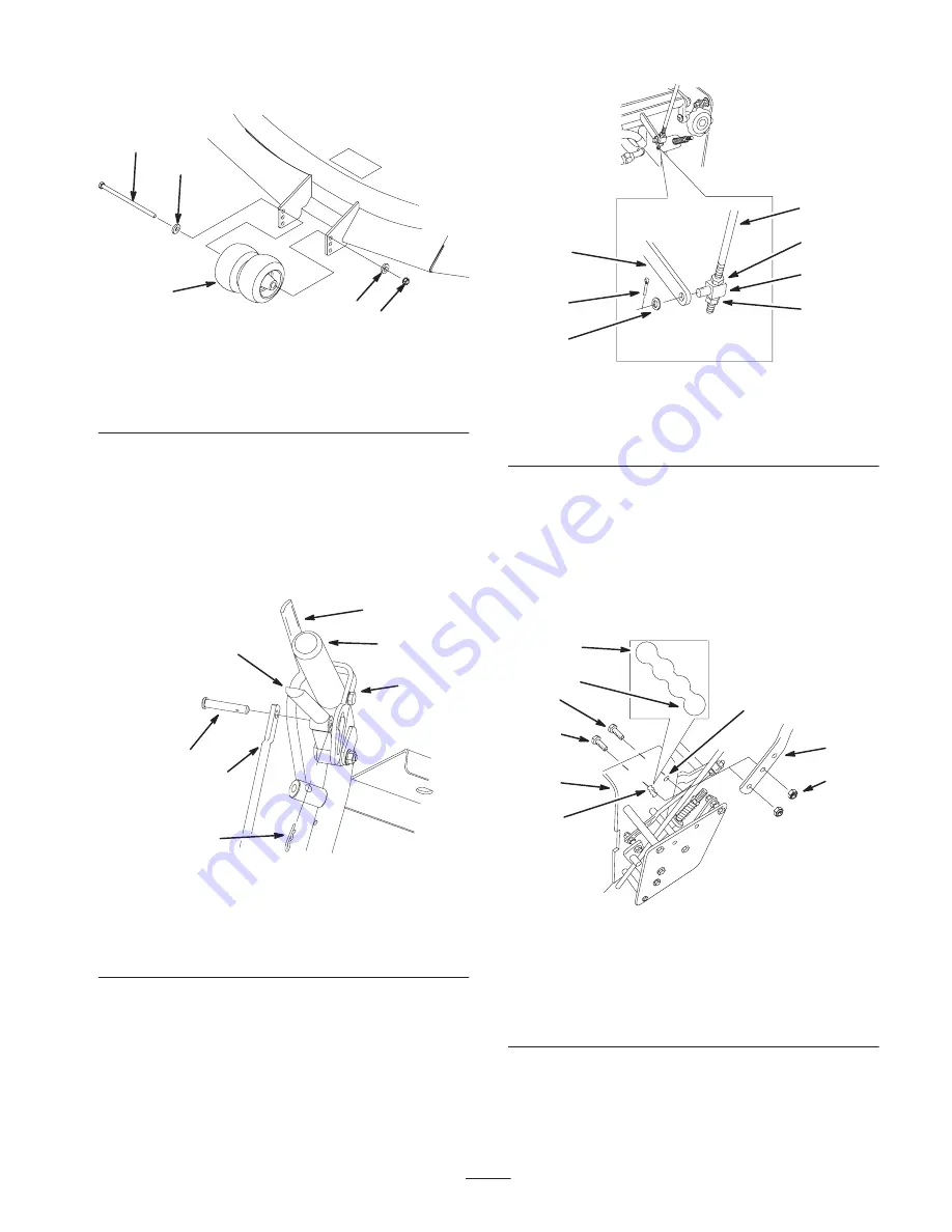
2. Loosen the nuts holding the swivel connected to the
speed control crank (Fig. 24).
m–6602
1
2
3
4
5
3
6
Figure 24
1.
Speed control rod
2.
Swivel
3.
Nut
4.
Speed control crank
5.
Cotter pin
6.
Washer
3. Loosen the upper flange bolts (3/8 x 1 inch) and flange
nut securing handle to rear frame (Fig. 25).
4. Remove the lower flange bolts (3/8 x 1 inch) and
flange nuts securing handle to rear frame (Fig. 25).
5. Pivot handle to desired operating position and install
lower flange bolts (3/8 x 1 inch) and flange nuts into
mounting holes. Tighten all flange bolts.
m–6600
7
8
9
2
1
3
5
6
4
Figure 25
1.
Handle assembly
2.
Rear frame
3.
Flange nut, 3/8 inch
4.
Flange bolt, 3/8 x 1 inch
5.
Upper mounting hole
6.
Lower mounting holes
7.
Low position
8.
High position
9.
Flange bolt, 3/8 x
1–1/4 inch
6. Adjust the swivel on the speed control rod and tighten
the nuts against the swivel (Fig. 24).
Summary of Contents for 30436
Page 7: ...7 Slope Chart...
Page 8: ...8...


