


Important:
The inside diameter of the bushings
may collapse slightly when installed. If the
caster wheel fork does not slide into the new
bushings, ream both bushings to an inside
diameter of 1.126 inch (29 mm).
11. Grease the fitting on the carrier frame mounting
tube using No. 2 general purpose lithium base or
molybdenum base grease.
Servicing the Caster Wheel
and Bearings
The caster wheels rotate on a roller bearing supported by
a spanner bushing. If the bearing is kept well lubricated,
wear will be minimal. Failure to keep the bearing well
lubricated will cause rapid wear. A wobbly caster wheel
usually indicates a worn bearing.
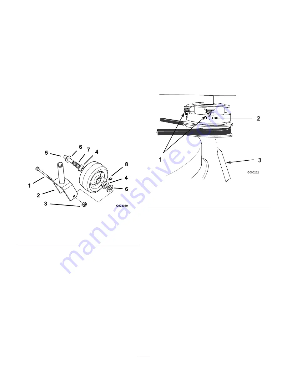
1. Remove the locknut and wheel bolt holding the
caster wheel to the caster fork (Figure 34).
Figure 34
1.
Wheel Bolt
5.
Spanner Bushing
2.
Caster fork
6.
Wheel spacer
3.
Locknut
7.
Roller Bearing
4.
Bushing
8.
Grease fitting
2. Remove one bushing, then pull the spanner bushing
and roller bearing out of the wheel hub (Figure 34).
3. Remove the other bushing from the wheel hub
and clean any grease and dirt from the wheel hub
(Figure 34).
4. Inspect the roller bearing, bushings, spanner bushing
and inside of the wheel hub for wear. Replace any
defective or worn parts (Figure 34).
5. To assemble, place one bushing into the wheel hub.
Grease the roller bearing and spanner bushing and
slide them into the wheel hub. Place the second
bushing into the wheel hub (Figure 34).
6. Install the caster wheel into the caster fork and
secure with the wheel bolt and locknut. Tighten the
locknut until the spanner bushing bottoms against
the inside of the caster forks (Figure 34).
7. Grease the fitting on the caster wheel.
Adjusting the Electric Clutch
Service Interval:
Every 100 hours
The clutch is adjustable to ensure proper engagement
and proper braking.
1. To adjust the clutch, tighten or loosen the lock nuts
on the flange studs (Figure 35).
Figure 35
1.
Adjusting nut
3.
Feeler gauge
2.
Slot
2. Check adjustment by inserting a feeler gauge through
the slots next to the studs (Figure 35).
3. The proper disengaged clearance between the clutch
plates is 0.012-0.024 inch (0.30-0.60 mm). It will be
necessary to check this clearance at each of the three
slots to ensure the plates are parallel to each other.
29
Summary of Contents for 30072
Page 41: ...Schematics Electrical Schematic Rev 41...
Page 42: ...Notes 42...
Page 43: ...Notes 43...