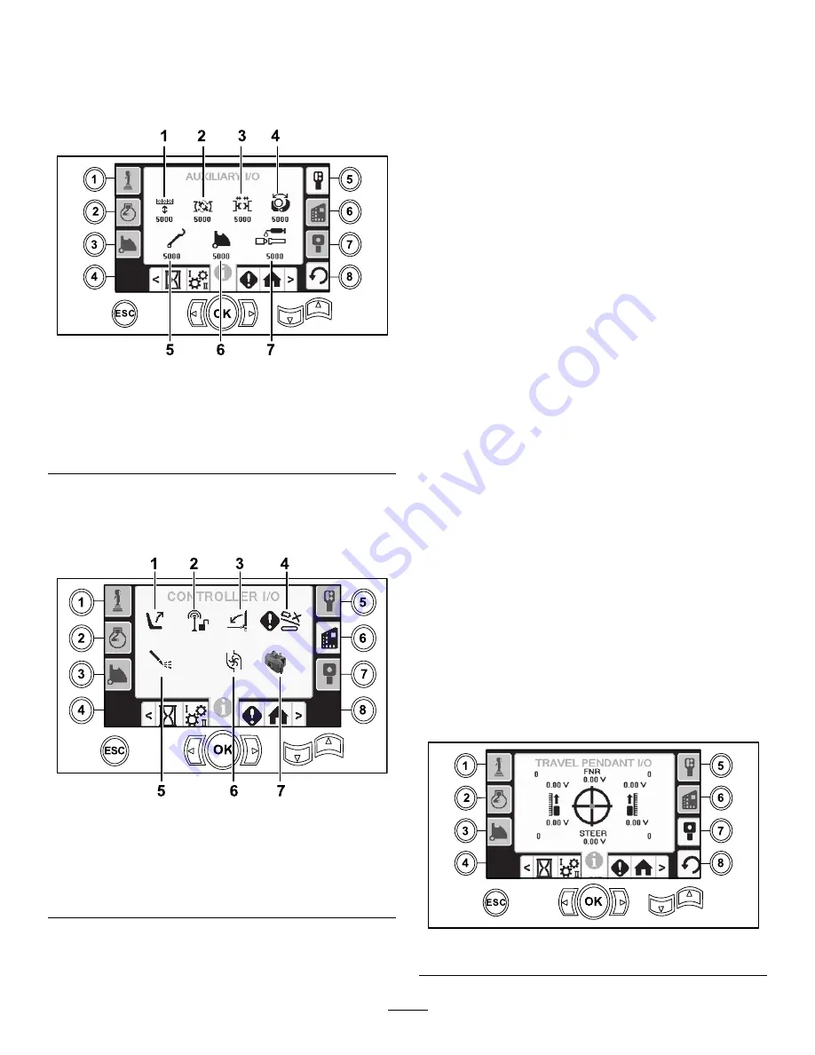
Auxiliary I/O Screen
To access this screen push button 5 on the I/O screen.
All icons change from black to green when you
operate the associated functions.
g213173
Figure 77
1.
Raise/Lower elevator
5.
Loader arm
2.
Breakout wrench
6.
Rotate pipe cam
3.
Upper or lower wrench
7.
TJC grease
4.
Gripper
Controller I/O Screen
To access this screen push button 6 on the I/O screen.
g213147
Figure 78
1.
Seat switch
5.
Mud pump status
2.
Exit side lockout
6.
Mud pump flow
3.
Pedestrian gate
7.
Processor indicator
4.
Cam override input
Seat switch icon:
shows an arrow out when the
operator seat is empty; the switch shows a figure icon
when you are in the operator seat.
•
Shows the seat with an arrow when the operator
seat is unoccupied
•
Shows the seat with a figurine when the operator
seat is occupied
Exit side lockout icon:
changes from black to green
when in operation.
Pedestrian gate icon:
•
Shown in the
UP
position with a figurine: the gate
is not in the correct position for drilling
•
Shown in the
DOWN
position: the gate is correctly
positioned for drilling
Cam override input icon:
turns green when the
override button is pushed on the joystick.
Mud pump status icon:
•
Black: mud pump is off
•
Yellow: mud pump is in standby
•
Green: mud pump is in on
•
Green with 100: mud pump is in max flow
Mud pump flow icon:
indicates the input from the
rocker switch on the joystick.
•
When the rocker switch is actuated up, the
indicator turns green with a blue up/increase arrow.
•
When the rocker switch is actuated down, the
indicator turns green with a blue down/decrease
arrow.
•
The icon is black when the rocker switch is not
pressed.
Processor indicator icon:
shows a red X to indicate
a problem with the expansion processor located next
to the main controller.
Travel Pendant I/O Screen
To access this screen push button 7 on the I/O screen.
The travel pendant screen shows the voltage and
position of the joystick located on the pendant.
g213169
Figure 79
19


