background image

32

Draining the Fuel Tank

Danger

In certain conditions, gasoline is extremely
flammable and highly explosive. A fire or
explosion from gasoline can burn you and others
and can damage property.

Drain gasoline from the fuel tank when the

engine is cold. Do this outdoors in an open area.

Wipe up any gasoline that spills.

Never smoke when draining gasoline, and stay

away from an open flame or where a spark may

ignite the gasoline fumes.

1.

Lower the loader arm, stop the engine, and remove the

key.

2.

Syphon the gasoline from the tank using a pump type

syphon.

Servicing the Hydraulic

System

Replacing the Hydraulic Filter

Change the hydraulic filter:

After the first 8 operating hours.

After every 200 operating hours.

1.

Position traction unit on a level surface.

2.

Lower the loader arm, stop the engine, and remove the

key.

3.

Open the hood; refer to Opening the Hood, page 23.

Important


Do not substitute an automotive oil filter or

severe hydraulic system damage may result.

4.

Place a drain pan under the filter (Fig. 60).

5.

Remove the old filter (Fig. 60) and wipe the surface of

the filter adapter gasket clean.

6.

Apply a thin coat hydraulic fluid to the rubber gasket

on the replacement filter.

7.

Install the replacement hydraulic filter onto the filter

adapter (Fig. 60). Tighten it clockwise until the rubber

gasket contacts the filter adapter, then tighten the filter

an additional 3/4 turn.

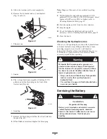
1

m–7465

Figure 60

1. Hydraulic filter

8.

Clean up any spilled fluid.

9.

Start the engine and let it run for about two minutes to

purge air from the system.

10.

Stop the engine and check for leaks.

Hydraulic fluid escaping under pressure can
penetrate skin and cause injury. Fluid injected
into the skin must be surgically removed within a
few hours by a doctor familiar with this form of
injury or gangrene may result.

Keep your body and hands away from pin hole

leaks or nozzles that eject high pressure

hydraulic fluid.

Use cardboard or paper to find hydraulic leaks,

never use your hands.

Warning

11.

Check the fluid level in the hydraulic tank (refer to

Checking the Hydraulic Fluid, page 12) and add fluid

to raise the level to mark on dipstick. Do not over fill

the tank.

12.

Close the hood.

Changing the Hydraulic Fluid

Change the hydraulic fluid after every 400 operating hours

or yearly.

1.

Position the traction unit on a level surface.

2.

Raise the loader arm, install the cylinder lock, stop the

engine, and remove the key.

3.

Open the hood; refer to Opening the Hood, page 23.

Summary of Contents for 22308

Page 1: ...Operator s Manual Original Instructions EN Register your product at www Toro com Form No 3354 653 Dingo TX 413 Compact Utility Loader Model No 22308 260000001 and Up...

Page 2: ...tents Page Introduction 2 Safety 3 Safe Operating Practices 3 Slope Chart 6 Safety and Instruction Decals 7 Setup 8 Loose Parts 8 Charging the Battery 9 Specifications 9 Attachments 9 Stability Data 1...

Page 3: ...capable of amputating hands and feet Always follow all safety instructions to avoid serious injury or death Engine exhaust contains carbon monoxide an odorless deadly poison that can kill you Do not r...

Page 4: ...may become unstable which may result in loss of control Do not carry a load with the arm raised Always carry loads close to the ground Do not over load the attachment and always keep the load level w...

Page 5: ...es Unplug the charger before connecting or disconnecting it from the battery Wear protective clothing and use insulated tools Keep all parts in good working condition and all hardware tightened Replac...

Page 6: ...6 Slope Chart Note This page may be copied for personal use only M 4402...

Page 7: ...s Safety decals and instructions are easily visible to the operator and are located near any area of potential danger Replace any decal that is damaged or lost 106 9450 106 9453 100 6101 100 6135 100...

Page 8: ...ing position Loose Parts Note Use the chart below to verify all parts have been shipped Description Qty Use Battery post bolt Battery post nut 2 2 Connect the battery Engine Manual Training video 1 1...

Page 9: ...s Fig 2 5 Install the battery cables to the positive and negative posts of the battery using the battery post bolts and nuts provided 6 Ensure that the protective boot covers the positive battery post...

Page 10: ...with the attachment installed find the degree of slope that corresponds to the stability ratings of the attachment Example If the attachment has a Front Uphill rating of B a Rear Uphill rating of D a...

Page 11: ...on a truck or trailer from a portable container rather than from a gasoline dispenser nozzle If a gasoline dispenser nozzle must be used keep the nozzle in contact with the rim of the fuel tank or co...

Page 12: ...1 Park the traction unit on a level surface lower the loader arm and stop the engine 2 Remove the key and allow the engine to cool 3 Open the hood refer to Opening the Hood page 23 4 Clean any debris...

Page 13: ...n Traction Unit Overview Figure 9 contains a front and back view of the traction unit Familiarize yourself with all of the traction unit components listed in Figure 9 11 1 5 7 8 4 6 2 10 m 7572 m 7571...

Page 14: ...choke lever forward After the engine starts regulate the choke to keep the engine running smoothly As soon as possible move the choke lever all the way rearward Note A warm engine requires little or n...

Page 15: ...sition such as forward and left you can move the loader arm and tilt the attachment at the same time Auxiliary Hydraulics Lever To operate a hydraulic attachment in the forward direction rotate the au...

Page 16: ...lectric fuel solenoid The fuel valve lever must be in the On position for the engine to run Fig 16 m 7556 1 2 Figure 16 1 Fuel valve in On position 2 Fuel valve in the Off position Hour Meter When the...

Page 17: ...or temperature is below freezing store the traction unit in a garage to keep it warmer and aid in starting Stopping the Engine 1 Move the throttle lever to the slow position Fig 19 A A B D C Figure 19...

Page 18: ...nder lock to the frame Fig 22 m 7460 1 2 Figure 21 1 Cylinder lock 2 Clevis and hairpin cotter 5 Place the cylinder lock over the cylinder rod and secure it with the clevis pin and hairpin cotter Fig...

Page 19: ...the mount plate should be tilted all the way back 6 Stop the engine 7 Engage the quick attach pins ensuring that they are fully seated in the mount plate Fig 24 Important If the pins do not rotate to...

Page 20: ...u contact hot components you may be burned Wear gloves when operating the hydraulic couplers Allow the traction unit to cool before touching hydraulic components Do not touch hydraulic fluid spills Ca...

Page 21: ...te or drive the traction unit on roadways Important When transporting the traction unit on a trailer always use the following procedure 1 Lower the loader arm 2 Stop the engine 3 Set the parking brake...

Page 22: ...ctions Check the spark plug 200 hours Change hydraulic filter1 3 5 300 hours Replace the spark plug 400 hours Inspect fuel lines for leaks Change hydraulic oil and filter1 Yearly Storage Check for loo...

Page 23: ...ny covers Opening the Hood 1 Turn the hood latch clockwise and swing the hood up Fig 30 m 7522 1 2 Figure 30 1 Hood latch turn clockwise 2 Hood swing up Closing the Hood Lower the hood and secure it b...

Page 24: ...d flush with the reference bar loosen the flange nut and bolt in the stem of the traction control Fig 34 m 7567 2 1 Figure 34 1 Traction control 2 Stem bolt and nut 5 Adjust the traction control so th...

Page 25: ...the traction control Fig 37 4 If the traction unit veers to the right loosen the left jam nut and adjust the tracking set screw on the front of the traction control Fig 37 m 7569 1 2 3 Figure 37 1 Se...

Page 26: ...portant To prevent engine damage always operate the engine with the complete foam and paper air cleaner assembly installed 1 Carefully slide the foam filter onto the paper filter Fig 39 2 Place the fi...

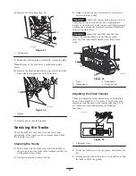
Page 27: ...emove dirt from each track system Important Ensure that you use high pressure water to wash only the track area Do not use a high pressure washer to clean the rest of the traction unit High pressure w...

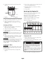
Page 28: ...k lug 6 Drive sprocket 7 Sprocket spacer 8 Road wheels 5 Push the tension wheel toward the rear of the unit to move the fork tube against the frame Fig 46 If it does not touch the frame continue turni...

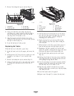
Page 29: ...he greased road wheel cap over the bolt head Fig 48 7 Secure the road wheel cap with the snap ring Fig 48 8 Repeat steps 3 through 7 for the other road wheels 9 Install each track guide to the tractio...

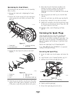
Page 30: ...ng the Spark Plug 1 Thread the spark plug into the spark plug hole 2 Tighten the spark plug until it compresses the metal washer and then seat it as follows If you are installing a used spark plug tig...

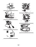
Page 31: ...31 m 7481 Figure 53 m 7482 Figure 54 m 7483 Figure 55 m 7484 Figure 56 m 7485 Figure 57 m 7486 Figure 58 m 7487 Figure 59...

Page 32: ...ulic fluid to the rubber gasket on the replacement filter 7 Install the replacement hydraulic filter onto the filter adapter Fig 60 Tighten it clockwise until the rubber gasket contacts the filter ada...

Page 33: ...fer to Checking Hydraulic Fluid page 12 13 Close the hood Checking the Hydraulic Lines After every 100 operating hours check the hydraulic lines and hoses for leaks loose fittings kinked lines loose m...

Page 34: ...ion 1 Clean the top of the battery with a paper towel 2 Lift off the filler caps Fig 64 3 Slowly pour distilled water into each battery cell until the level is up to the lower part of the tube Fig 64...

Page 35: ...battery refer to Servicing the Battery page 33 11 For storage over 30 days prepare the traction unit as follows A Add a petroleum based stabilizer conditioner to fuel in the tank Follow mixing instru...

Page 36: ...ler Engine loses power 1 Engine load is excessive 1 Reduce ground speed g p 2 The air cleaner is dirty 2 Clean the air cleaner 3 The oil level in crankcase is low 3 Add oil to the crankcase 4 The cool...

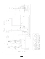
Page 37: ...37 Schematics Electrical Schematic...

Page 38: ...38 Hydraulic Schematic...

Page 39: ...duled for replacement as required maintenance in the written instructions must be warranted for the warranty period of two years If any such part fails during the period of warranty coverage it must b...

Page 40: ...onsumption through use unless found to be defective Examples of parts which are consumed or used up during normal Product operation include but are not limited to digging teeth tines spark plugs tires...

Reviews: