background image

Consumer
TimeCutter

The Toro Total Coverage Guarantee

A Two-Year Full Warranty

(Limited Warranty for Commercial Use)

Conditions and Products Covered

The Toro Company and its affiliate, Toro Warranty Company,
pursuant to an agreement between them, jointly promise to repair
any Toro Product used for normal residential purposes* if defective
in materials or workmanship. The following time periods apply
from the date of purchase:

Products

Warranty Period

All TimeCutter Mowers and
Attachments

2 year full warranty

All Batteries

1 year full warranty

This warranty covers both the cost of parts and labor, and
transportation within a fifteen mile radius of the servicing dealer.

This warranty applies to all consumer TimeCutter Mowers and
their attachments.

* Normal residential purposes means use of the product on the

same lot as your home. Use at more than one location is
considered commercial use, and the commercial use warranty
would apply.

Limited Warranty for Commercial Use

Toro Consumer Products and attachments used for commercial,
institutional, or rental use are warranted against defects in
materials or workmanship for the following time periods from the
date of purchase:

Products

Warranty Period

Air Cooled Gas Engines

90 day limited warranty

All other items

30 day limited warranty

Instructions for Obtaining Warranty Service

If you think that your Toro Product contains a defect in materials or
workmanship, follow this procedure:

1Contact any Toro Authorized or Master Service Dealer to

arrange service at their dealership. To locate a dealer
convenient to you, refer to the Yellow Pages of your telephone
directory (look under “Lawn Mowers”) or access our website at
www.Toro.com. U.S. Customers may also call toll free:
866–854–9035 to use our 24-hour Toro dealer locator system.

2Bring the product and your proof of purchase (sales receipt) to

the Service Dealer.

If for any reason you are dissatisfied with the Service Dealer’s
analysis or with the assistance provided, contact us at:

Customer Care Department, Consumer Division
Toro Warranty Company
8111 Lyndale Avenue South
Bloomington, MN  55420-1196
Toll Free: 866–216–6029 (U.S. customers)
Toll Free: 866–216–6030 (Canada customers)

Owner Responsibilities

You must maintain your Toro Product by following the maintenance
procedures described in the operator’s manual. Such routine
maintenance, whether performed by a dealer or by you, is at your
expense.

Items and Conditions Not Covered

There is no other express warranty except for special emission
system coverage on some products. This express warranty does
not cover:

Cost of regular maintenance service or parts, such as filters,
fuel, lubricants, tune-up parts, blade sharpening, brake and
clutch adjustments.

Any product or part which has been altered or misused or
required replacement or repair due to normal wear, accidents,
or lack of proper maintenance.

Repairs necessary due to improper fuel, contaminants in the
fuel system, or failure to properly prepare the fuel system prior
to any period of non-use over three months.

Pickup and delivery charges for distances beyond a fifteen
mile radius from an Authorized Toro Service Dealer.

All repairs covered by this warranty must be performed by an
Authorized Toro Service Dealer using Toro approved replacement
parts.

General Conditions

Repair by an Authorized Toro Service Dealer is your sole remedy
under this warranty.

Neither The Toro Company nor Toro Warranty Company is liable
for indirect, incidental or consequential damages in connection
with the use of the Toro Products covered by this warranty,
including any cost or expense of providing substitute equipment or
service during reasonable periods of malfunction or non-use
pending completion of repairs under this warranty.

Some states do not allow exclusions of incidental or consequential
damages, or limitations on how long an implied warranty lasts, so
the above exclusions and limitations may not apply to you.

This warranty gives you specific legal rights, and you may also
have other rights which vary from state to state.

Countries Other than the United States or Canada

Customers who have purchased Toro products exported from the United States or Canada should contact their Toro Distributor (Dealer)
to obtain guarantee policies for your country, province, or state. If for any reason you are dissatisfied with your Distributor’s service or
have difficulty obtaining guarantee information, contact the Toro importer. If all other remedies fail, you may contact us at Toro Warranty
Company.

Part No. 374-0061

Summary of Contents for 18-44 ZX TimeCutter

Page 1: ...Operator s Manual Original Instructions EN Register your product at www Toro com Form No 3350 165 18 44 ZX TimeCutter ZX Riding Mower Model No 74602 Serial No 240000001 and Up ...

Page 2: ...irst 13 Controls 13 Parking Brake 14 Starting and Stopping the Engine 14 Operating the Power Take Off PTO 15 Page The Safety Interlock System 15 Testing the Safety Interlock System 15 Driving Forward or Backward 16 Stopping the Machine 16 Adjusting the Height of Cut 16 Adjusting the Anti Scalp Rollers 17 Positioning the Seat 17 Adjusting the Motion Control Levers 18 Pushing the Machine by Hand 18 ...

Page 3: ... which means CAUTION WARNING or DANGER personal safety instruction Failure to comply with the instruction may result in personal injury or death Safe Operating Practices The following instructions are from ANSI standard B71 1 1998 This product is capable of amputating hands and feet and throwing objects Always follow all safety instructions to avoid serious injury or death General Operation Read u...

Page 4: ...gic accidents can occur if the operator is not alert to the presence of children Children are often attracted to the machine and the mowing activity Never assume that children will remain where you last saw them Keep children out of the mowing area and under the watchful care of another responsible adult Be alert and turn the machine off if children enter the area Before and while backing or chang...

Page 5: ... leave a running machine unattended Always turn off blades set parking brake stop engine and remove the ignition key before dismounting Keep hands feet hair and loose clothing away from attachment discharge area underside of mower and any moving parts while engine is running Do not touch equipment or attachment parts which may be hot from operation Allow to cool before attempting to maintain adjus...

Page 6: ...6 ...

Page 7: ...7 Slope Chart ...

Page 8: ...8 ...

Page 9: ...ecals and instructions are easily visible to the operator and are located near any area of potential danger Replace any decal that is damaged or lost 1 633354 1 Fast 2 Slow 3 Neutral 4 Reverse 106 0699 92 7108 92 7109 93 1122 98 3798 104 8008 ...

Page 10: ... 1 Engine 104 3641 1 Height of cut 104 8009 1 Throttle 2 Choke 3 Fast 4 Continuous variable setting 5 Slow 6 On 7 Off 8 Headlights 9 Engine stop 10 Engine run 11 Engine start 12 Ignition 104 8032 1 Height of cut ...

Page 11: ...mical burn hazard 4 Wear eye protection 5 Read the Operator s Manual 6 Keep bystanders a safe distance from the battery 7 Wear eye protection explosive gases can cause blindness and other injuries 8 Battery acid can cause blindness or severe burns 9 Flush eyes immediately with water and get medical help fast 10 Contains lead do not discard 107 7399 ...

Page 12: ... then refuel such equipment on a truck or trailer from a portable container rather than from a gasoline dispenser nozzle If a gasoline dispenser nozzle must be used keep the nozzle in contact with the rim of the fuel tank or container opening at all times until fueling is complete Gasoline is harmful or fatal if swallowed Long term exposure to vapors can cause serious injury and illness Avoid prol...

Page 13: ...ning To avoid loss of control and possibility of rollover Do not mow near drop offs or near water Do not mow slopes greater than 15 degrees Reduce speed and use extreme caution on slopes Avoid sudden turns or rapid speed changes 2 3 1 m 6491 Figure 2 1 Safe Zone use the Timecutter here 2 Use walk behind mower and or hand trimmer near drop offs and water 3 Water Controls Become familiar with all of...

Page 14: ... brake refer to Setting the Parking Brake page 14 3 Move the PTO power take off to Off Fig 6 1 m 4201 2 Figure 6 1 PTO On 2 PTO Off 4 Move the throttle lever to Choke before starting a cold engine Note A warm or hot engine may require choking After the engine starts move the throttle lever to Fast 5 Turn the ignition key to Start to energize the starter When the engine starts release the key Impor...

Page 15: ...fety interlock system is designed to prevent the engine from starting unless The parking brake is engaged The PTO is disengaged The motion control levers are in the neutral locked position The safety interlock system also is designed to stop the engine when the traction controls are moved with the parking brake on or if you rise from the seat when the PTO is engaged Testing the Safety Interlock Sy...

Page 16: ...l Backward 1 Move the levers to the center unlocked position 2 To go backward slowly pull the motion control levers rearward Fig 10 To go straight apply equal pressure to both motion control levers Fig 10 To turn release the pressure on the motion control lever toward the direction you want to turn Fig 10 To stop push the motion control levers to neutral Stopping the Machine To stop the machine mo...

Page 17: ... the key 2 After adjusting the height of cut remove the nut and washer while holding the stud with a wrench Fig 12 Note Do not remove the wheel nut and washer Fig 12 m 4167 1 2 3 4 5 Figure 12 1 Gage wheel 2 Stud 3 Washer 4 Nut 5 Wheel nut and washer Do not remove 3 Select a hole so that the gage wheel is positioned to the nearest corresponding height of cut desired Fig 12 4 Install the stud nut a...

Page 18: ...15 3 Disengage the parking brake to push the machine m 5139 1 2 Figure 15 1 Position for pushing the machine 2 Position for operating the machine To Operate the Machine Pull each bypass lever up and pull them completely out Push the levers down Fig 15 Note The machine will not drive unless the bypass levers are pulled out Side Discharge The mower has a hinged grass deflector that disperses clippin...

Page 19: ... mow less frequently If you cannot mow for an extended period first mow at a high cutting height then mow again two days later at a lower height setting Cutting Speed To improve cut quality use a slower ground speed Avoid Cutting Too Low If the cutting width of the mower is wider than the mower you previously used raise the cutting height to ensure that uneven turf is not cut too short Long Grass ...

Page 20: ... system 1 Service the paper air cleaner 1 Change the oil filter 2 Replace the fuel filter Replace the spark plug Before storage Perform all maintenance procedures listed above before storage Drain the fuel tank Charge the battery and disconnect the battery cables Paint any chipped surfaces 1More often in dusty dirty conditions 2More often when operating the engine under heavy load or in high tempe...

Page 21: ... Metal end 4 Screw the oil dipstick fully onto the fill hole Unscrew the dipstick pull it out and look at the metal end If the oil level is low slowly pour only enough oil into the fill hole to raise the level to but not over the Full mark on the dipstick Important Do not overfill the crankcase with oil because the engine may be damaged Changing and Draining the Oil 1 Start the engine and let it r...

Page 22: ...lacement filter Fig 19 1 2 3 1256 Figure 19 1 Oil filter 2 Gasket 3 Adapter 4 Install the replacement oil filter to the filter adapter Turn the oil filter clockwise until the rubber gasket contacts the filter adapter then tighten the filter an additional 1 2 to 3 4 turn Fig 19 5 Fill the crankcase with the proper type of new oil refer to Changing and Draining the Oil page 21 Servicing the Air Clea...

Page 23: ...ed air or liquids such as solvent gas or kerosene Replace the paper element if it is damaged or cannot be cleaned thoroughly Installing the Foam and Paper Elements Important To prevent engine damage always operate the engine with the complete foam and paper air cleaner assembly installed 1 Place the foam element and paper element into the blower housing Note Make sure that the rubber seal is flat ...

Page 24: ...rp blades throughout the cutting season because sharp blades cut cleanly without tearing or shredding the grass blades Tearing and shredding turns grass brown at the edges which slows growth and increases the chance of disease Check the cutter blades daily for sharpness and for any wear or damage File down any nicks and sharpen the blades as necessary If a blade is damaged or worn replace it immed...

Page 25: ...blade that is bent or damaged could break apart and could seriously injure or kill you or bystanders Always replace bent or damaged blade with a new blade Never file or create sharp notches in the edges or surfaces of blade Warning Removing the Blades The blades must be replaced if a solid object is hit if the blade is out of balance or the blade is bent To ensure optimum performance and continued...

Page 26: ...t Grease more frequently when operating conditions are extremely dusty or sandy Grease with No 2 general purpose lithium base or molybdenum base grease How to Grease 1 Disengage the PTO stop the engine and remove the key 2 Clean the grease fittings with a rag Make sure to scrape any paint off of the front of the fitting s 3 Connect a grease gun to the fitting Pump grease into the fittings until gr...

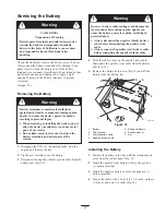
Page 27: ...he PTO set the parking brake stop the engine and remove the key 2 Tip the seat forward to see the battery 3 Disconnect the negative black ground cable from the battery post Fig 32 Incorrect battery cable routing could damage the tractor and cables causing sparks Sparks can cause the battery gasses to explode resulting in personal injury Always disconnect the negative black battery cable before dis...

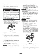
Page 28: ...and cause corrosion 2 Clean the top of the battery with a paper towel 3 Remove the vent caps from the battery Fig 33 4 Slowly pour distilled water into each battery cell until the electrolyte level is up to the Upper line Fig 33 on the battery case Important Do not overfill the battery because electrolyte sulfuric acid can cause severe corrosion and damage to the chassis 5 Wait five to ten minutes...

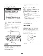
Page 29: ...ain into a gas can or drain pan Note Now is the best time to install a new fuel filter because the fuel tank is empty 6 Install the fuel line onto the fuel filter Slide the hose clamp close to the fuel filter to secure the fuel line Fig 35 Replacing the Fuel Filter Replace the fuel filter after every 100 operating hours or yearly whichever occurs first Never install a dirty filter if it is removed...

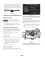
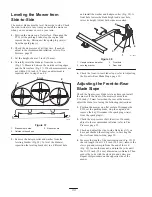
Page 30: ...ole raises its height Adjust both sides as required 1 4 3 2 m 5177 Figure 38 1 Hairpin cotter and washer 2 Leveling bracket 3 Front hole 4 Rear hole 6 Check the front to rear blade slope refer to Adjusting the Front to Rear Blade Slope page 30 Adjusting the Front to Rear Blade Slope Check the front to rear blade level any time you install the mower If the front of the mower is more than 5 16 inch ...

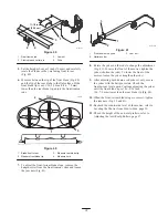
Page 31: ... trunion yokes and loosen the jam nuts Fig 41 m 5178 1 2 3 Figure 41 1 Front trunion rod yoke 2 Hairpin cotter 3 Jam nut 8 Rotate the yokes on the rods to change the adjustment Fig 41 To raise the front of the mower tighten the yokes shorten the rods To lower the front of the mower loosen the yokes lengthen the rods 9 After adjusting both trunion rod yokes evenly secure the yokes with the hairpin ...

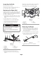
Page 32: ... spring from the spring eye bolt Caution 5 Route the new belt through the idler arm and around the idler pulley Fig 42 2 1 4 3 7 5 6 m 4197 Figure 42 Top View 1 Outer nut 2 Idler pulley 3 Idler arm 4 Spring eye bolt 5 Spring 6 1 8 inch 3 mm 7 Mower belt 6 Pull the idler pulley in the direction shown in Figure 42 and route the belt onto the other pulleys Fig 43 Note Check to ensure that the length ...

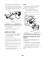
Page 33: ...kets onto the mounting pins and secure them with the washers and hairpin cotters Fig 45 6 Attach the front trunion rods to the tractor with the clevis pins and hairpin cotters Fig 44 7 Install the mower belt onto the engine pulley refer to Replacing the Mower Belt page 32 Fuse The electrical system is protected by fuses It requires no maintenance however if a fuse blows check the component circuit...

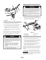
Page 34: ...or s or bystander s direction and result in serious injury Also contact with the blade could occur Never operate the lawn mower unless you install a cover plate a mulch plate or a grass chute and catcher Warning 1 Remove the locknut bolt and spring holding the deflector to the mower brackets Fig 48 Remove the damaged or worn grass deflector m 1783 1 5 3 6 4 2 Figure 48 1 Mower bracket 2 Spring hoo...

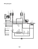
Page 35: ...RT R R R BATTERY 10A F3 OR OR 1 2 TO HEADLIGHT HARNESS BK OR GND Y GN W SOLENOID GN BN PK PTO SW2 SHOWN IN OFF POSITION BROWN BK BLACK BLUE BU GREEN GN BN GREY GY OR ORANGE WIRE COLOR CODES W WHITE VIO VIOLET PINK PK RED R TAN T YELLOW Y PK Y I 1 7 4 X A B S X KEY SWITCH PN 88 9830 OFF NO CONNECTION ON B I A AND X Y START B I S IGNITION SW1 25A F2 R VIO BU OR 30A F1 PK W I S Y KEY SW TERMINAL VIEW...

Page 36: ...til it stops D Choke or prime the engine Start and run the engine until it will not start Operate the primer if equipped several times to ensure no fuel remains in the primer system E Dispose of fuel properly Recycle as per local codes Important Do not store stabilizer conditioned gasoline over 90 days 11 Remove the spark plug s and check its condition refer to Spark Plug page 23 With the spark pl...

Page 37: ...rrect 6 Install a new correctly gapped spark plug s 7 There is dirt in fuel filter 7 Replace the fuel filter 8 Dirt water or stale fuel is in fuel system 8 Contact an Authorized Service Dealer 9 There is incorrect fuel in the fuel tank 9 Drain the tank and replace the fuel with the proper type 10 The oil level in the crankcase is low 10 Add oil to the crankcase The engine loses power 1 The engine ...

Page 38: ...lade spindle is bent 6 Contact an Authorized Service Dealer Uneven cutting height 1 The blade s is not sharp 1 Sharpen the blade s g g 2 A cutting blade s is are bent 2 Install a new cutting blade s 3 The mower is not level 3 Level the mower from side to side and front to rear 4 An anti scalp wheel is not set correctly 4 Adjust the anti scalp wheel height 5 The underside of the mower is dirty 5 Cl...

Page 39: ...39 ...

Page 40: ...216 6030 Canada customers Owner Responsibilities You must maintain your Toro Product by following the maintenance procedures described in the operator s manual Such routine maintenance whether performed by a dealer or by you is at your expense Items and Conditions Not Covered There is no other express warranty except for special emission system coverage on some products This express warranty does ...

Reviews: