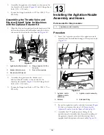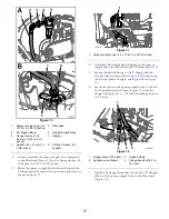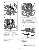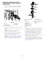
Figure 89
1.
Flange
(right-boom-section valve)
3.
Flange clamp
2.
Gasket
4.
90° elbow (with pressure
port)
Installing the Supply Hose—Machines
with the Optional Spray Gun Kit
1.
Apply PTFE tape to the threads (
) of the
straight barbed fitting (1/2 inch).
Figure 90
1.
PTFE tape
2.
Straight barbed fitting (1/2
inch)
2.
Assemble the straight barbed fitting (1/2 inch) into the
quick-connect fitting (socket) as shown in
.
Figure 91
1.
Hose—1.3 x 762 cm (1/2 x
300 inches)
3.
Straight barbed fitting (1/2
inch)
2.
Hose clamp
4.
Quick-connect fitting
(socket)
3.
Assemble the hose—1.3 x 762 cm (1/2 x 300 inches)
with a hose clamp 6 to 11 mm (1/4 to 7/16 inch) onto
the straight barbed fitting (
4.
Assemble the quick-connect fitting (socket) of the hose
to the quick-connect fitting of the flange shutoff valve
(
).
Figure 92
1.
Quick-connect fitting
(flange shutoff valve)
3.
Retainer
2.
Hose—1.3 x 762 cm (1/2 x
300 inches)
4.
Quick-connect fitting
(socket)
5.
Secure the quick-connect fittings of the hoses and the
flange shutoff valve with the retainer provided with the
quick-connect fitting of the hose (
).
6.
Route the supply hose forward along the sprayer tank
toward the spray-gun bracket, and secure the hose to
the tank frame with the 3 cable ties (
43
Summary of Contents for 136-0372
Page 61: ...Schematics Flow Diagram Rev A 61...
Page 62: ...Notes...
Page 63: ...Notes...
Page 64: ......


