Installing the Shutoff Valve for the
Optional Spray Gun Kit or the Electric
Hose Reel Kit
1.
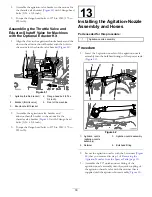
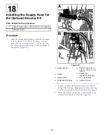
Remove the flange clamp that secures the gasket and
end cap to the flange of the right spray valve (
Figure 87
1.
Gasket
4.
Flange clamp
2.
End cap (ported)
5.
Tube coupler
3.
Flange (right spray valve)
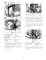
2.
Remove the tube coupler from the port of the end cap
(
).
Note:
Retain the flange clamp, gasket, and tube
coupler. You no longer need the end cap.
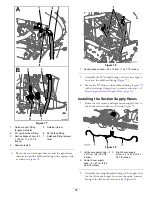
3.
Remove the retainer that secures the straight barbed
fitting (3/4 inch) to the flange shutoff valve, and
remove the barbed fitting (
Note:
Retain the retainer and straight barbed fitting for
installation in
Installing the Supply Hose—Machines
with the Optional Electric Hose-Reel Kit (page 44)
.
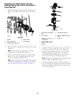
Figure 88
1.
90° elbow (with pressure
port)
5.
Flanged shutoff valve
2.
Tube coupler
6.
Straight barbed fitting (3/4
inch)
3.
Gasket—25 x 35 mm (1 x
1-3/8 inches)
7.
Retainer
4.
Flange clamp—40 to
64 mm (1-9/16 to 2-1/2
inches)
4.
Assemble the tube coupler that you removed in step
into the pressure port of the 90° elbow (
5.
Assemble the flanged shutoff valve to the 90° elbow
(with pressure port) and gasket—25 x 35 mm (1 x
1-3/8 inches) with the flange clamp—40 to 64 mm
(1-9/16 to 2-1/2 inches) as shown in
Note:
Ensure that the handle of the shutoff valve and
the tube coupler are aligned 180° apart.
6.
Assemble the flange of the 90° elbow (with pressure
port) to the flange of the right-boom section valve with
the gasket and flange clamp that you removed in step
as shown in
.
42
Summary of Contents for 136-0372
Page 61: ...Schematics Flow Diagram Rev A 61...
Page 62: ...Notes...
Page 63: ...Notes...
Page 64: ......


