background image

California Proposition 65 Warning Information

What is this warning?

You may see a product for sale that has a warning label like the following:

WARNING:

Cancer and Reproductive Harm—www.p65Warnings.ca.gov.

What is Prop 65?

Prop 65 applies to any company operating in California, selling products in California, or manufacturing products that may be sold in or brought into
California. It mandates that the Governor of California maintain and publish a list of chemicals known to cause cancer, birth defects, and/or other
reproductive harm. The list, which is updated annually, includes hundreds of chemicals found in many everyday items. The purpose of Prop 65 is to
inform the public about exposure to these chemicals.

Prop 65 does not ban the sale of products containing these chemicals but instead requires warnings on any product, product packaging, or literature with
the product. Moreover, a Prop 65 warning does not mean that a product is in violation of any product safety standards or requirements. In fact, the
California government has clarified that a Prop 65 warning “is not the same as a regulatory decision that a product is ‘safe’ or ‘unsafe.’” Many of these
chemicals have been used in everyday products for years without documented harm. For more information, go to

https://oag.ca.gov/prop65/faqs-view-all

.

A Prop 65 warning means that a company has either (1) evaluated the exposure and has concluded that it exceeds the “no significant risk level”; or (2)
has chosen to provide a warning based on its understanding about the presence of a listed chemical without attempting to evaluate the exposure.

Does this law apply everywhere?

Prop 65 warnings are required under California law only. These warnings are seen throughout California in a wide range of settings, including but not
limited to restaurants, grocery stores, hotels, schools, and hospitals, and on a wide variety of products. Additionally, some online and mail order
retailers provide Prop 65 warnings on their websites or in catalogs.

How do the California warnings compare to federal limits?

Prop 65 standards are often more stringent than federal and international standards. There are various substances that require a Prop 65 warning
at levels that are far lower than federal action limits. For example, the Prop 65 standard for warnings for lead is 0.5 μg/day, which is well below
the federal and international standards.

Why don’t all similar products carry the warning?

Products sold in California require Prop 65 labelling while similar products sold elsewhere do not.

A company involved in a Prop 65 lawsuit reaching a settlement may be required to use Prop 65 warnings for its products, but other companies
making similar products may have no such requirement.

The enforcement of Prop 65 is inconsistent.

Companies may elect not to provide warnings because they conclude that they are not required to do so under Prop 65; a lack of warnings for a
product does not mean that the product is free of listed chemicals at similar levels.

Why does Toro include this warning?

Toro has chosen to provide consumers with as much information as possible so that they can make informed decisions about the products they buy and
use. Toro provides warnings in certain cases based on its knowledge of the presence of one or more listed chemicals without evaluating the level of
exposure, as not all the listed chemicals provide exposure limit requirements. While the exposure from Toro products may be negligible or well within the
“no significant risk” range, out of an abundance of caution, Toro has elected to provide the Prop 65 warnings. Moreover, if Toro does not provide these
warnings, it could be sued by the State of California or by private parties seeking to enforce Prop 65 and subject to substantial penalties.

Rev A


Summary of Contents for 04831

Page 1: ...Form No 3445 354 Rev B Greensmaster e1021 Greensmower Model No 04831 Serial No 400000000 and Up Register at www Toro com Original Instructions EN 3445 354 ...

Page 2: ... the product properly and safely Visit www Toro com for product safety and operation training materials accessory information help finding a dealer or to register your product Whenever you need service genuine Toro parts or additional information contact an Authorized Service Dealer or Toro Customer Service and have the model and serial numbers of your product ready Figure 1 identifies the locatio...

Page 3: ...nsport Wheels 22 Engaging or Disengaging the Transmission 22 Maintaining the Lithium Ion Battery Pack 23 Caring for the Battery Pack 23 Understanding the Battery Charger 24 Maintenance 26 Maintenance Safety 26 Recommended Maintenance Schedule s 26 Daily Maintenance Checklist 27 Pre Maintenance Procedures 27 Preparing the Machine for Maintenance 27 Electrical System Maintenance 28 Electrical System...

Page 4: ...on Allow the machine to cool before adjusting servicing cleaning or storing it Improperly using or maintaining this machine can result in injury To reduce the potential for injury comply with these safety instructions and always pay attention to the safety alert symbol which means Caution Warning or Danger personal safety instruction Failure to comply with these instructions may result in personal...

Page 5: ...Warning do not operate this machine unless you are trained 2 Pull down to apply the brake 7 Warning wear hearing protection 3 Parking brake locked 8 Thrown object hazard keep bystanders away 4 Parking brake unlocked 9 Warning stay away from moving parts keep all guards and shields in place 5 Warning read the Operator s Manual 10 Do not tow the machine decal139 5613 139 5613 1 Warning do not discar...

Page 6: ...Compliance 1 Read or view the items before operating the machine Note Determine the left and right sides of the machine from the normal operating position 1 Adjusting and Installing the Cutting Unit Parts needed for this procedure 1 Cutting unit order separately contact your authorized Toro distributor 1 Coupler 1 Reel driveshaft 4 Socket head screw Disassembling the Reel Drive Assembly Perform th...

Page 7: ...the loose parts bag Take care to not damage the seal g343495 Figure 6 1 Nut 3 New reel driveshaft 2 Pulley 4 Key 2 Install the key into the driveshaft keyway Figure 6 3 Install the pulley Figure 6 4 Use the nut to secure the new reel driveshaft to the assembly Figure 6 5 Torque the nut to 37 to 45 N m 27 to 33 ft lb 6 Install the belt and tension the belt by applying 4 to 5 N m 35 to 40 in lb to t...

Page 8: ...ut 5 Use the previously removed hardware to install the reel drive assembly to the cutting unit Figure 8 6 Ensure that the coupler Figure 8 can easily move back and forth on the transmission driveshaft 2 Installing the Transport Wheels Optional Parts needed for this procedure 1 Transport Wheel Kit order separately contact your authorized Toro distributor Procedure To install the transport wheels y...

Page 9: ...mounting rod 4 Mounting the Battery Charger on a Wall Optional No Parts Required Procedure You can mount the charger on a wall using the wall mount key holes cut into the back of the unit Use screws that have a 6 mm 1 4 inch diameter shaft and a head diameter of 11 mm 0 45 inch Important Survey your work area and determine a location that best meets the criteria for safe and effective operation of...

Page 10: ...ery pack 2 Kickstand 5 Transport wheel axle 3 Handle 6 Cutting unit Controls g308000 Figure 11 1 Clutch bail 6 Hour meter 2 Cutting unit drive lever 7 Lift assist handle 3 Parking brake latch 8 InfoCenter 4 Service brake lever 9 Key switch 5 Speed control 10 ...

Page 11: ...parking brake Pull the service brake lever toward the handle Cutting Unit Drive Lever Use the cutting unit drive lever Figure 11 to engage or disengage the cutting unit Engage the cutting unit With the clutch bail in the neutral disengaged position move the lever down Disengage the cutting unit Move the lever up Hour Meter The hour meter Figure 11 records the total number of hours that the key swi...

Page 12: ...raise the machine Attempting to raise the machine onto the kickstand any other way can cause injury CUTTING UNIT SERVICE position To prevent the machine from tipping backward when removing the cutting unit lower the kickstand and push out the spring pin so that it keeps the kickstand in the position shown in Figure 14 g343381 Figure 13 1 Lift assist handle 3 Kickstand TRANSPORT WHEEL SERVICE posit...

Page 13: ...sories Replacement parts and accessories made by other manufacturers could be dangerous and such use could void the product warranty Operation Note Determine the left and right sides of the machine from the normal operating position Before Operation Before Operation Safety General Safety Never allow children or untrained people to operate or service the machine Local regulations may restrict the a...

Page 14: ...196 inch 3 6 mm 0 142 inch 2 8 mm 0 112 inch Adjusting the Reel Speed Use the reel speed control knob Figure 15 to adjust the reel speed High reel speed Rotate the knob so that the H on the knob is directed toward the front of the machine Low reel speed Rotate the knob so that the L on the knob is directed toward the front of the machine g341648 Figure 15 1 Reel speed control knob shown in the hig...

Page 15: ...ne page 17 4 Set the speed control to SLOW tip the front of the machine up gradually engage the traction drive and slowly increase the machine speed 5 Adjust the speed control to operate the mower at the desired ground speed and transport the machine to the desired destination Transporting the Machine Using a Trailer Use a trailer to transport the machine a considerable distance Use caution while ...

Page 16: ...d fall accident Keep your hands and feet away from the cutting unit Look behind and down before backing up to be sure of a clear path Use extreme caution when reversing or pulling the machine toward you Use care when approaching blind corners shrubs trees or other objects that may obscure your vision Stop the cutting unit whenever you are not mowing Disengage the drive to the cutting unit and shut...

Page 17: ... refer to Controls page 10 1 Ensure that the T handle connector on the main wire harness is connected to the main power supply connector 2 Ensure that the clutch bail is disengaged 3 Move the key switch to the ON position Using the InfoCenter LCD Display The InfoCenter LCD display shows information about your machine such as the current battery charge the speed various diagnostics and other inform...

Page 18: ...Lists the current battery charge as a percent of capacity Battery Current Lists the instantaneous current delivered by the battery in Amps Battery Volts Lists the battery potential in volts Total Usage Lists the total amount of battery usage in amp hours Capacity List the current battery capacity in amp hours Charge Cycles Lists the total amount of battery charge cycles A charge cycle is defined b...

Page 19: ... the display contact your authorized Toro distributor for assistance in resetting the display Operating Tips Important Grass clippings act as a lubricant when mowing Operating the cutting unit excessively without grass clippings can damage the cutting unit Mow the greens in a straight back and forth direction across the green Avoid circular mowing or turning the machine on the greens areas to prev...

Page 20: ...low the machine to cool before adjusting servicing cleaning or storing it Clean grass and debris from the machine to help prevent fires Allow the machine to cool before storing the machine in any enclosure Do not store the machine where there is an open flame spark or pilot light such as on a water heater or on other appliances Battery and Charger Safety General Improperly using or maintaining the...

Page 21: ... watches when working with a lithium ion battery A lithium ion battery can produce enough current to cause a severe burn Never operate the charger without good visibility or light Use an appropriate extension cord If the power supply cord is damaged while it is plugged in disconnect the cord from the wall receptacle and contact an authorized Toro distributor for a replacement Unplug the charger fr...

Page 22: ...stand Engaging or Disengaging the Transmission You can disengage the drum from the transmission to allow the machine to be maneuvered Disengage the transmission when you need to move the machine without starting the machine e g performing maintenance in an enclosed area Before you operate the machine ensure that you engage the transmission 1 Locate the traction engagement lever on the transmission...

Page 23: ...3 000 ft2 Note Your results may vary depending on the distance you need to transport the machine the contact setting of the bedknife and other factors as discussed in this section To achieve maximum life and use from your battery apply the following care guidelines Do not open the battery pack There are no user serviceable parts inside If you open the pack you will void your warranty The pack is p...

Page 24: ...the charger with wet hands or while standing in water Important Check the power supply cord periodically for holes or cracks in the insulation Do not use a damaged cord Do not run the cord through standing water or wet grass 1 Insert the charger plug on the power supply cord into the matching input power socket on the charger WARNING A damaged charger cord can cause an electrical shock or a fire T...

Page 25: ...nitoring the Charging Process and Troubleshooting Note The LCD status display displays messages during the course of charging Most are routine If there is a fault the error indicator light will flash amber or light solid red An error message will appear in the LCD display Figure 23 1 digit at a time starting with the letter E or F for example E 0 1 1 To correct an error refer to Troubleshooting pa...

Page 26: ...intenance adjustment keep your hands feet clothing and any parts of the body away from the cutting unit attachments and any moving parts Keep bystanders away Clean grass and debris from the cutting unit drive motor and battery to help prevent fires Keep all parts in good working condition Replace all worn damaged or missing parts and decals Keep all hardware tight to ensure that the machine is in ...

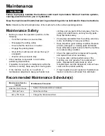
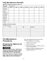
Page 27: ...nance WARNING While you are maintaining or adjusting the machine someone could start the machine Accidentally starting the machine could seriously injure you or other bystanders Release the traction bail engage the parking brake remove the key and disconnect the battery before you do any maintenance Perform the following before servicing cleaning or making any adjustments to the machine 1 Park the...

Page 28: ...lems with your battery pack contact your authorized Toro distributor for help WARNING The battery pack contains high voltage which could burn or electrocute you Do not attempt to open the battery pack Do not place anything in the connector of the battery pack other than the wire harness connector that came with the product Use extreme care when handling a battery pack with a cracked case Only use ...

Page 29: ...1 Turn off the machine and disconnect the battery pack 2 Remove the 4 screws Figure 26 that secure the battery pack cover and remove the cover g341636 Figure 26 1 Screws 2 Fuse block 3 Check the fuses in the fuse block Figure 27 g300604 Figure 27 1 30A main power supply circuits 3 3A optional LED work light circuit 2 3A logic power supply circuits 4 Open slot 4 If any fuse is blown replace them wi...

Page 30: ... the breather vent and adapter assembly and tighten it to 12 to 15 N m 110 to 130 in lb Controls System Maintenance Adjusting the Service Parking Brake Adjust the service parking brake if it slips during operation 1 Engage the parking brake 2 Using a spring scale apply a force on the service brake lever Figure 29 The parking brake should release when you attain a force of 16 to 18 kg 35 to 40 lb I...

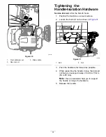
Page 31: ...e machine on a level surface 2 Loosen the bolt and nut as shown in Figure 31 g343384 Figure 31 1 Bolt 2 Nut 3 Push the handle as far forward as possible 4 While supporting the handle torque the bolt and nut that you loosened in step 2 to 68 to 75 N m 50 to 55 ft lb Note Have an assistant help you to support the handle or torque the hardware 5 Release the handle 31 ...

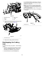
Page 32: ...the reel drive assembly to the side plate Figure 32 g333187 Figure 32 1 Socket head screw 4 Spring washer 2 Spacer 5 Nut 3 Washer 3 Remove the reel drive assembly flat washers spring washers and spacers from the side plate Figure 32 4 Align the cutting unit to the frame 5 Use 4 socket head screws to secure the cutting unit to the frame Figure 33 g343380 Figure 33 1 Socket head screw 6 Use the prev...

Page 33: ... Access Backlap Kit Model 139 4342 and use a backlapping machine Contact your authorized Toro distributor to acquire this kit Use the InfoCenter to enter Backlap Mode To enter Backlap Mode select BACKLAP from the SERVICE menu Follow the InfoCenter prompts to backlap the cutting unit Note Once the bail is released Backlap Mode is disengaged You can use the bail catch fork shipped in the loose parts...

Page 34: ... machine refer to Cleaning the Machine page 34 Important You can wash the machine with mild detergent and fresh clean water Do not pressure wash the machine Avoid excessive use of water especially near the shift lever plate the InfoCenter the power center and the machine power connector 2 Check and tighten all fasteners Repair or replace any part that is worn or damaged 3 Paint all scratched or ba...

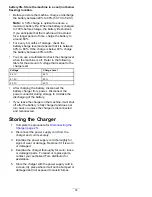
Page 35: ...vel Voltage Charge Level 52 1V 60 51 4V 50 50 7V 40 After charging the battery disconnect the battery charger from power Disconnect the power connector during storage to minimize the discharging of the battery If you leave the charger on the machine it will shut off after the battery is fully charged and does not turn back on unless the charger is disconnected and reconnected Storing the Charger 1...

Page 36: ... Connect charger to an AC source that provides stable AC between 85 270 VAC 45 65 Hz Code E 0 2 4 1 Charger failed to initialize 1 The charger has failed to turn on properly Disconnect the AC input and battery connection for 30 seconds before retrying Code E 0 2 5 1 Low AC voltage oscillation error 1 The AC source is unstable Could be caused by undersized generator or severely undersized input cab...

Page 37: ... for marketing purposes Retention of your Personal Information Toro will keep your personal information as long as it is relevant for the above purposes and in accordance with legal requirements For more information about applicable retention periods please contact legal toro com Toro s Commitment to Security Your personal information may be processed in the US or another country which may have le...

Page 38: ...vered for the duration of the original product warranty and become the property of Toro Toro will make the final decision whether to repair any existing part or assembly or replace it Toro may use remanufactured parts for warranty repairs Deep Cycle and Lithium Ion Battery Warranty Deep cycle and Lithium Ion batteries have a specified total number of kilowatt hours they can deliver during their li...

Page 39: ...hip for a period of 4 years Over time battery consumption reduces the amount of energy capacity Amp hours available per full charge Energy consumption varies due to operating characteristics accessories turf terrain adjustments and temperature Tier Years Days 1 2 0 730 2 2 5 731 910 3 3 911 1095 4 3 5 1096 1275 5 4 1276 1460 374 0330 Rev B ...

Page 40: ...to restaurants grocery stores hotels schools and hospitals and on a wide variety of products Additionally some online and mail order retailers provide Prop 65 warnings on their websites or in catalogs How do the California warnings compare to federal limits Prop 65 standards are often more stringent than federal and international standards There are various substances that require a Prop 65 warnin...

Reviews: