2.
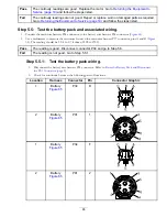
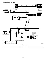
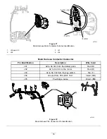
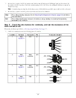
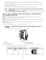
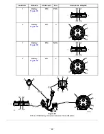
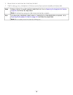
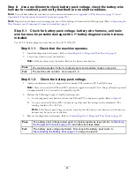
Check the resistance of the main contactor coil (
A.
Disconnect the wire from the main contactor J04 terminal.
B.
Check resistance across the coil terminals J03, and J04. Normal resistance is 180 to 195 ohms.
C.
Connect the wire to the main contactor J04 terminal.
Pass
The coil resistance and coil circuit continuity tested good. Go to
and follow the steps listed.
Fail
The coil resistance and/or coil circuit continuity tests failed. Repair and or replace malfunctioning
parts. Go to
Returning the Equipment to Service (page 19)
and follow the steps listed.
Step 6:
Replace the TEC-2401 (conditional)
If steps 4 and 5 passed, and Fault 9 repeated immediately after returning the equipment to service, then replace the TEC-2401.
Go to
Returning the Equipment to Service (page 19)
and follow the steps listed.
Step 7:
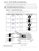
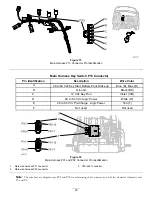
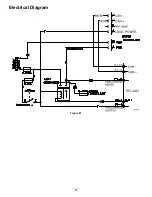
Use a multimeter to check for 42 to 64 Vdc at the motor controller.
Note:
You will find additional wire harness and connector information in
Appendix A: Wire Harnesses (page 113)
and
Appendix B: Toro Electronic Controller Connections (page 135)
.
1.
Rotate the key switch to the O
FF
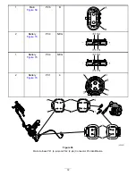
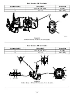
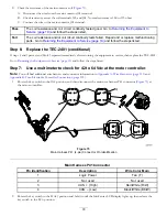
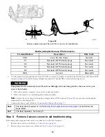
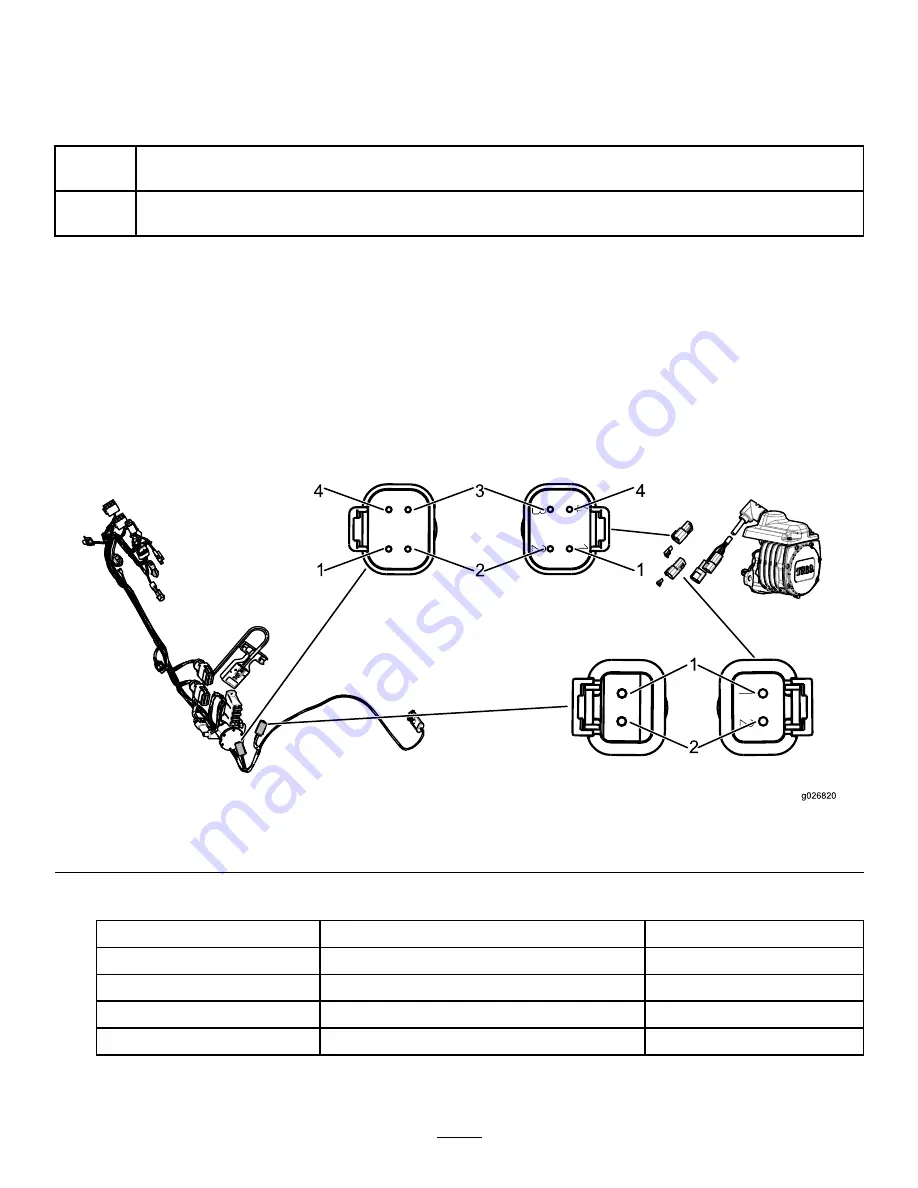
position, and then disconnect the main wire harness P41 connector (
) at
the motor controller.
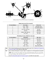
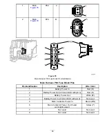
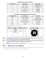
Figure 75
Main Harness P41 (4-pin) Connector Pin Identification
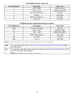
Main Harness P41 Connector
Pin Identification
Description
Wire Color Main
1
Logic Power
Tan (T)
2
Not used
Not used
3
CAN + (High)
Red/White (R/W)
4
CAN – (Low)
Black/White (BK/W)
2.
Rotate the key switch to the S
TART
position and hold it until the InfoCenter LCD display lights up, then release the
key switch to the R
UN
position.
79

