background image

18 


322 Railroad Ave North, Kent, WA 98032


Phone (800) 246-8132 Fax (253) 854-

8003 

Or visit our website: 

www.TorkLift.com 

 
Dear Valued Customer, 

 
Thank you for making TorkLift your choice for truck, camper packages and 

accessories for your vehicle. By choosing TorkLift products, you have chosen a 
company that has been serving the RV industry for nearly 40 years and whose 
name has become synonymous with strength, quality and advanced design and 

installation. 
 

Please take a few moments of your time to complete the Product Registration 
Warranty Card on the next page. When registering your newly purchased TorkLift 
products, you can be assured that your contact information is secure and that you 

and your product are getting the attention and respect that you deserve.  
 

Thank you again for choosing TorkLift quality products. 
 

Register for your lifetime warranty and receive a free Torklift 

International gift. 


To Fax: Send copies of the questionnaire, warranty card and receipt to 

253-854-8003 


To E-mail: Send copies of the questionnaire, warranty card and receipt to 

[email protected] 


To Mail: Send to Torklift International 322 Railroad Ave North, Kent, WA 98032


Summary of Contents for A9003

Page 1: ...1 IMPORTANT OWNER OPERATOR INSTALLATION INSTRUCTIONS A9003 A9004 A9005 A9103 A9104 A9105 Version Number 4 Date 9 11 2019 By CW TECH SUPPORT 800 246 8132 ...

Page 2: ...cle handling characteristics We have found that airbags used in conjunction with StableLoads have allowed operators to lower air bag pressure by 50 or more Only pressurize suspension air bags enough to level the truck Warning Fire Danger Some entry doors are equipped with a gas strut or other device limiting the travel of the door In some cases these devices are installed to prevent the door from ...

Page 3: ...nting Bracket A9003 P2 R 1 3 8 SS Flat Washer SAE 8949 4 3 8 Nylon Flat Washer 11748 4 3 8 16 x 1 1 4 SS Button Head Cap Screw 15010 2 3 8 16 SS Nylock Hex Nut 10564 2 1 4 14 x 1 SS Self Drilling Screw 11083 4 3 8 ID 3 4 OD x 1 2 Nylon Spacer 11747 2 12 24 x 3 4 SS Button Head Screw 13594 6 12 24 SS Nylock Hex Nut 13596 6 12 SS SAE Flat Washer 13595 6 ...

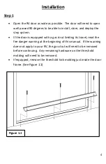
Page 4: ...is equipped with a gas strut limiting its travel read the fire danger warning at the beginning of this manual If the warning does not apply to your RV the gas strut will need to be removed before continuing Any remaining hardware on the threshold molding will need to be removed If equipped remove the threshold kick molding just inside the door frame See Figure 1 1 Figure 1 1 ...

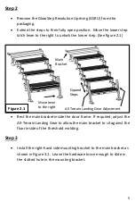
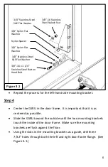
Page 5: ...nside the door frame If required adjust the All Terrain Landing Gear to allow the main bracket to sit against the floor inside of the threshold molding Step 3 Install the right hand side mounting bracket to the main bracket as shown in Figure 3 1 Leave the hardware loose enough to slide in the slotted hole in the mounting bracket Figure 2 1 Move lever to the right Expand Steps All Terrain Landing ...

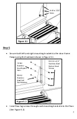
Page 6: ...f the door frame Make sure the mounting brackets are flush against the floor Using the slots in the mounting brackets as a guide drill three 7 32 holes through both the left and right door frame flange See Figure 4 1 Figure 3 1 3 8 16 Stainless Steel Nylock Nut 3 8 Nylon Flat Washer 3 8 Stainless Steel SAE Flat Washer 3 8 16 x 1 1 4 Stainless Steel Button Head Bolt Nylon Spacer 3 8 Nylon Flat Wash...

Page 7: ...sing the hardware shown in Figure 5 1 Install two lag screws through each mounting bracket into the floor See Figure 5 2 Figure 4 1 Drill 3x 7 32 Holes Figure 5 1 3X 12 Stainless Steel Nylock Nuts 3X 12 Stainless Steel SAE Flat Washers 12 24 x 3 4 Stainless Steel Button Head Screws ...

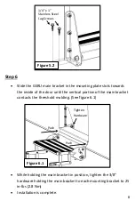
Page 8: ...rtion of the main bracket contacts the threshold molding See figure 6 1 While holding the main bracket in position tighten the 3 8 hardware holding the main bracket to each mounting bracket to 25 in lbs 2 8 Nm Installation is complete Figure 5 2 1 4 x 1 Stainless Steel Lag Screws Figure 6 1 Tighten Hardware Push Push ...

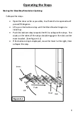
Page 9: ...90 degrees Lift up on the bottom step until the Main Bracket begins to rotate up Push the bottom step towards the RV to collapse the steps The studs on the sides of the steps should engage in the slots on the main bracket See Figure A 1 If the bottom step is deployed move the lever to the right then collapse the step Figure A 1 Lift Push Stud Slot Lever ...

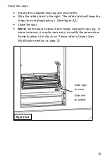
Page 10: ...the steps from rotating back out See Figure A 2 Close the door NOTE Screen door to door frame flange clearances do vary In some instances it may be necessary to modify the screen door frame to allow it to fully close Please refer to Screen Door Modification section on page 15 Figure A 2 Slide right to store Slide left to unlock ...

Page 11: ...p Revolution Uprising All Terrain Landing Gear Adjustment When the steps are angled up towards the RV o Depress the tubing button and adjust the All Terrain Landing Gear feet up until the steps are level See figure B 1 If the bottom step is deployed it may be necessary to store it for the steps to be leveled When the steps are angled down away from the RV o Depress the tubing button and adjust the...

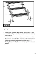
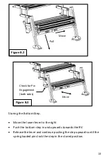
Page 12: ...main step assembly See Figure B 2 Release the lever and expand the bottom step as far as possible Move the step back and forth to make sure both spring loaded pins have locked the bottom step into position See Figure B 3 Warning Failure to verify the step is locked in position may result in injury Figure B 1 Depress Slide Slide Depress ...

Page 13: ...he right Push the bottom step in and upwards towards the RV Release the lever and continue pushing the step upwards until the spring loaded pins lock the step in the stored position Figure B 2 Move Pull Figure B 3 Check for Pin Engagement both sides Move ...

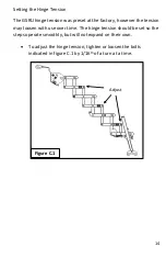
Page 14: ...ory however the tension may loosen with use over time The hinge tension should be set so the steps operate smoothly but will not expand on their own To adjust the hinge tension tighten or loosen the bolts indicated in figure C 1 by 1 16th of a turn at a time Figure C 1 Adjust ...

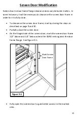
Page 15: ...fully close To clearance the screen door frame start by storing the steps as described on page 9 and 10 Partially close the screen door On the hinged side of the screen door mark the screen door frame 1 4 above and 1 4 below where the GSRU rests against the door frame flange See Figure D 1 Fully open the screen door to gain better access to the marked area Figure D 1 Mark Screen Door Frame ...

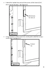
Page 16: ...und the corners of the frame 3 16 then Connect the lines See Figure D 2 Using a Dremel or similar rotary tool cut along the marked lines using a cutoff wheel See figure D 3 Marked area for removal Figure D 2 Figure D 3 Finished Cut ...

Page 17: ...t will replace FREE OF CHARGE any part which proves defective in material or workmanship when presented to Torklift TRANSPORTATION CHARGES PREPAID by purchaser at the address above THIS WARRANTY IS LIMITED TO DEFECTIVE PARTS REPLACEMENT ONLY LABOR CHARGES AND OR DAMAGE INCURRED IN INSTALLATION OR REPLACEMENT AS WELL AS INCIDENTAL AND CONSEQUENTIAL DAMAGES CONNECTED THEREWITH ARE EXCLUDED This warr...

Page 18: ...s of your time to complete the Product Registration Warranty Card on the next page When registering your newly purchased TorkLift products you can be assured that your contact information is secure and that you and your product are getting the attention and respect that you deserve Thank you again for choosing TorkLift quality products Register for your lifetime warranty and receive a free Torklif...

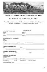
Page 19: ...OFFICIAL WARRANTY REGISTATION CARD 322 Railroad Ave North Kent Wa 98032 Please fill out this form completely and return to Torklift within 30 days of purchase accompanied by a copy of your original receipt ...

Reviews: