


PowerHub
TM
User Manual, Version 1.2
19
7
POWERHUB DETAIL
7.1
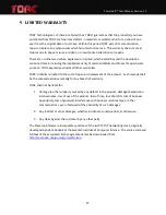
Front View
Item Description
1
Output Indicator LEDs (x8)
2
Input Fans (x2)
3
10-32 Threaded Mounting locations (x4)
4
Master ON/OFF Switch, Circuit Breaker
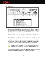
Figure 8: Front View of the PowerHub
On the front face of the PowerHub, there are indicator LEDs (1) for each of the eight outputs.
These LEDs will illuminate GREEN when the corresponding output is enabled and RED if an
overcurrent fault is detected on the output. If the LED is off, the output is
OFF
. The left most
LED corresponds to output one and the right most LED corresponds to output eight.
The two fans (2) provide forced air cooling of the internal electronics and are turned on
automatically anytime an output is active. Internal fan speed monitoring ensures both fans are
functioning properly. The direction of air flow through the PowerHub is from front to rear.
Four mounting holes (3) on the face of the PowerHub are the primary method of attaching the
device mounting brackets. These holes are threaded for a 10-32 machine screw.
The rocker switch (4) on the front of the PowerHub serves as a dual purpose as the Master
ON/OFF switch and a resettable circuit breaker. This breaker interrupts all input current to the
PowerHub, protecting against a short circuit condition. With the Master Switch in the ON
position, the PowerHub is powered and outputs are under software control via the Ethernet
interface. If the Master Switch is in the OFF position, the PowerHub is disabled and in a zero
power mode.


