background image

Shanghai TopXGun Robotics Co.,Ltd.

6th Floor,3rd. Building,Elite City,No. 57, AnDemen Street,Yuhua District,Nanjing,China,210012

TEL:

025-86467760

FAX:

025-52323411

What you need to know before using?
Please strictly follow the requirements of this manual to install and use this product.
The TopXGun robotics official website (www.TopXGun.com) has a special page
about M2. You can login to the web for the latest product information, technical
support and user manuals. It is recommended that you should download and use the
latest version of the user manual. If this manual is updated, no further notice.

You can also obtain product usage information or technical support through the
official customer service phone, WeChat client, and Weibo client. We are dedicated to
serve you. Due to different production batches, the appearance or function parameters
are slightly different. However, these do not affect the normal use of the product.

Before using this product, please install the corresponding assistant software to your
computer or mobile device. This manual needs to be used together with the
corresponding assistant software. For more information, please refer to the
instruction text on the assistant software. If there is inconsistency with the user
manual, the assistant software shall prevail.

Disclaimer
Please read the instructions carefully before using this product. Once you start using
this product, you are deemed to have accepted and accepted all the contents of this
statement. This product is suitable for people 18 years of age or older.

This product is a flight control system for multi-rotor aircraft. In the case of normal
power supply and correct connection, it can provide users with an excellent flying
experience. When using this flight control system to debug parameters and perform
firmware upgrades, we strongly recommend that you remove the propeller and ensure
that the power supply is normal and that the corresponding functional module wiring
is correct. When using it, be sure to keep away from people, dangerous goods, and
fragile items.In case of direct or indirect personal injury and property damage caused
by the following reasons during use, TopXGun will not be liable for compensation:

1. The user did not assemble and use according to the requirements of this manual;
2. The user manipulates the aircraft in the event of poor physical or mental conditions
such as drinking, drug use, fatigue, etc.;
3. The user actively or intentionally manipulates the aircraft to create damage;
4. The user has used the non-overheaded accessories to personally modify the
product and caused the aircraft to fail to work properly;
5. Injury caused by user error or subjective misjudgment;
6. The damage caused by the aircraft's natural wear, circuit aging, etc.

Summary of Contents for M2

Page 1: ...e City No 57 AnDemen Street Yuhua District Nanjing China 210012 TEL 025 86467760 FAX 025 52323411 M2 Multirotor Flight Controller User Manual V1 1 Using Firmware V2 0 Assistant Software V2 0 Revision date 2018 04 Shanghai TopXGun Robotics Co Ltd www TopXGun com ...

Page 2: ...hall prevail Disclaimer Please read the instructions carefully before using this product Once you start using this product you are deemed to have accepted and accepted all the contents of this statement This product is suitable for people 18 years of age or older This product is a flight control system for multi rotor aircraft In the case of normal power supply and correct connection it can provid...

Page 3: ...responsibility Intellectual property The intellectual property rights of this product and manual are owned by Shanghai TopXGun Robotics Co Ltd Without written permission no organization or individual may copy reproduce or distribute in any form If you need to quote you must indicate the source and you must not modify delete or cite this manual Certification This product has passed FCC CE RoHS cert...

Page 4: ...pass module l Automotive gyro high precision high reliability 40 125 full temperature calibration strong anti vibration performance l Automotive accelerometer high precision high reliability l GPS compass module and LIU module IP65 protection class l Industrial grade reliability surge protection anti static level 8000V l Independent control of flight controller core components to ensure flight saf...

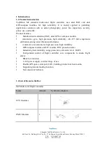
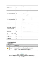
Page 5: ...e 2 GPS Compass module 2 USB cable 1 Micro USB conversing to 4PIN flat plug line 1 Steering line 8 3M double sided adhesive 6 Certification 1 Quick guide 1 1 3 Symbol Description Universal symbols Symb ol Significan ce Instructions Notes Text starting with this sign indicates potential risks Ignoring these texts can result in equipment damage data loss or other unpredictable consequences ...

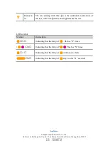
Page 6: ...11 Instructio ns The text starting with this sign is the additional information of the text which emphasizes and supplements the text LED symbol Symbol Instructions N Indicating that the lamp of flashes N times N Indicating that the lamp of flashes N times Indicating that the lamp of continues to flash N Indicating that the lamp of stays on for N seconds ...

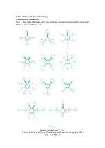
Page 7: ...y No 57 AnDemen Street Yuhua District Nanjing China 210012 TEL 025 86467760 FAX 025 52323411 2 Installation and Commissioning 2 1 Hardware installation Step 1 Determine the multi rotor type and head orientation and install the motor and blades as shown in Figure 2 1 ...

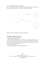
Page 8: ...tions Figure 2 2 Connection diagram of the main control circuit Installation connection instructions l FCU master controller installation Installation location requirements When installed the M2 mark is printed with the side facing up and the direction of the arrow on the housing remains the same as that of the aircraft head In order to achieve the best flying effect the main controller should be ...

Page 9: ...rrow pointing in the direction of the head during installation 6 COM1 interface digital interface 7 COM2 interface Open SDK API port 8 CAN2 interface as an API port for extending other peripherals 9 M1 M8 Electrical adjustment interface If the ESC with BEC output is used the middle BEC power output line must be cut off Connecting GND Connecting 5V Connecting signal output l PMU module installation...

Page 10: ...ds during installation and use l LIU module installation Install the LIU module in an easy to observe position such as the rear of the aircraft without obstructing the USB port And use the attached 3M glue to connect it to any CAN expansion port on the PMU 2 2 Assistant software installation and debugging Preparation before installation and commissioning The M2 flight controller supports PC tuning...

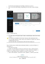
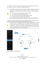
Page 11: ...rotates clockwise when looking from above 3 For upper and lower coaxial rotors green indicates the upper rotor and blue indicates the lower rotor 4 The bottom blue arrow indicates the direction of the aircraft nose Step 4 Set the remote controller input method and calibrate it as shown in Figure 2 5 and Figure 2 6 1 Select the receiver type 2 Create a new fixed wing or multi rotor model on the rem...

Page 12: ... slider goes right l The elevator goes down and the pitch slider goes right l Throttle lever goes up throttle slider goes right If the directions are not consistent click REV to set the reverse direction 4 Switch 5 8 channel switches Check whether the stop position corresponds to the control mode one by one and whether the return flight map is normal If the receiver is not an SBus receiver the rem...

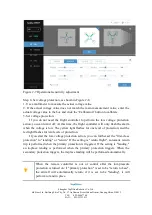
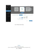
Page 13: ... Step 5 Set the sensitivity as shown in Figure 2 7 It is forbidden to adjust the sensitivity during the flight It is recommended to adjust the unlocked state 1 Select the closest wheelbase to the rack The M2 flight controller uses the default sensitivity to get a better flight status 2 According to the assistant software s instructions combine the aircraft s own state to fine tune the sensitivity ...

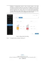
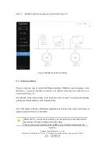
Page 14: ...ght controller will only flash the alarm when the voltage is low The yellow light flashes for one level of protection and the red light flashes for two levels of protection If you start the low voltage protection action you can further set the first class protection to landing or return If the setting is return flight automatic return trip is performed when the primary protection is triggered If t...

Page 15: ... pressure protection at any time by toggling 5 channel mode switch back and forth For the security reasons it is strongly recommended that the appropriate low voltage value is set to ensure the enough batteries for the return of the aircraft If the voltage is too low and the aircraft is short of power it will cause the serious consequences such as a crash Fig 2 8 voltage protection setting Step 7 ...

Page 16: ...Shanghai TopXGun Robotics Co Ltd 6th Floor 3rd Building Elite City No 57 AnDemen Street Yuhua District Nanjing China 210012 TEL 025 86467760 FAX 025 52323411 Fig 2 9 Motor related setting ...

Page 17: ...American you must perform to unlock it as shown in the fig 2 11 and lock it as shown in the fig 2 12 The throttle of the aircraft stays at its lowest level for at least 3 seconds after landing and the aircraft performs to lock automatically After M2 flight controller calibration adjustment is finished the motor will rotate in proper sequence when it is unlocked When the No 1 motor starts running y...

Page 18: ...d be removed before calibration The operating steps for Electric speed controller are as follows Step 1 Push throttle to the highest level At this time status indicator indicates current status GPS Compass module and flight mode Step 2 Switch 5 channel switches back and forth at lowest level and highest level about 6 to 10 times until red light on status indicator is on Step 3 Keep the throttle po...

Page 19: ... into normal indication Operation chart is shown in the fig 2 13 Fig 2 13 Electric speed controller calibration 图 2 13 电调校准 After ESC is calibrated successfully the motor will rotate in sequence when it is unlocked otherwise recalibration is required Because DJI series ESC idle speed is higher when you apply the recommended idle speed to unlock the motor there will be phenomenon without idling spe...

Page 20: ... 14 compass calibration 2 5 Horizontal Calibration The operation steps of horizontal calibration is as follows Step 1 Lay the flight on the horizontal ground in order to ensure the fuselage level and viberation free Step 2 Perform the outer eight characters lock on the remote controller and hold for more than 10 seconds until the status indicator starts flashing alternately with the blue green lig...

Page 21: ...njing China 210012 TEL 025 86467760 FAX 025 52323411 The operation chart is shown in Figure 2 15 fig 2 15 horizontal calibration If the aircraft is still severely side slipping after taking off with gesture mode in the course of a subsequent flight it is recommended to be reperformed horizontal calibration ...

Page 22: ...lue and throttle input occupies the maximum power GPS mode Roll pitch Roll pitch tilt angle corresponds to the lever input size but the corresponding directional flight velocity is limited to be below the maximum horizontal velocity 12 m s yaw Yaw speed corresponds to yaw lever input size Throttle Keep Throttle corresponding height and the amplitude of the throttle corresponds to the rising descen...

Page 23: ...satellite 7 and low precision G1P1 0 1 0 2 0 1 1 6 0 5 GPS mode GPS satellite 7 and high precision G1G2 0 1 0 2 0 1 1 6 0 5 Self driving mode R5 0 1 0 3 2 5 5 Self driving mode reach the waypoint G1R1 0 1 0 2 0 1 1 6 0 5 l the nose heading locked G1B2 0 1 0 2 0 1 1 6 0 5 Returning point locked B10 0 1 0 1 5 10 Take off point have recorded Module indication R1B1 0 1 0 1 5 10 System initialization c...

Page 24: ...idiary IMU indicator light seven colors when enabled the green light is always on when backuped the blue light is always on when it is abnormal the red light is always on 3 2 3 GMU indicator light instruction GMU There is a light position at the front arrow 1 GMU Before starting to search satellite the blue light is always on 2 GMU After starting to search satellite successfully green breath lamp ...

Page 25: ...electrical connection secure or not l whether the type of aircraft is selected correctly or not Self test when it is electrified For power on checking steps as follows please refer to indicator light instructions about the meaning of LED status indicator light Step 1 Turn on the remote controller and then connect to the main power supply After the main controller is switched on avoid shaking the a...

Page 26: ...inue to push the throttle until the aircraft is off the ground Step 4 Feel the handling of each control channel below 2 meters height if the response is normal you can continue to tap the maximum potential of flight controller After flight you must check that if the temperature of the forward motor and the reverse motor are the same If the temperature is not consistent the aircraft may have the ph...

Page 27: ...n or land in place according to the settings in the adjusting parameter software To set protection measures for primary low voltage protection please see step 6 in the installation and testing step After the two stage low voltage protection is triggered the LED alarm is The aircraft will automatically land in place l When the low voltage protection function is implemented it can only be switched t...

Reviews: