background image

47

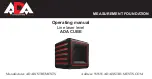
Level Sensor LS-80A / 80B

Beam receiving 
window

Buzzer sound 
switch

(Quiet/Loud/OFF)

Display

Index

Detective 
precision switch

Two leveling precision 
options are available, normal 
precision and high precision. 
By pressing this switch, the 
precision options are 
switched alternately. Confirm 
the precision choice by the 
indicator. (Normal precision 
is set when turning on the 
power switch.)

Power switch

Buzzer speaker

Display

(Only LS-80A)

Auto-cut off function 

The power will be turned off automatically if no laser beam is detected within 
approximately 30 minutes. (To turn the sensor on again, press the power switch.)

Summary of Contents for RL-100 2S

Page 1: ...INSTRUCTION MANUAL ROTATING LASER RL 100 2S 31485 90050 ESC MENU ENT RL 100 2S X Y...

Page 2: ...nterference including interference that may cause undesired operation of the device The installer of this radio equipment must ensure that the antenna is located or pointed such that it does not emit...

Page 3: ...trument against shock When transporting the instrument provide some protection to minimize risk of shock Heavy shocks may affect beam accuracy Sudden changes of temperature A sudden change in temperat...

Page 4: ...c Physical damage refers to extensive damage to buildings or equipment and furniture Display Meaning WARNING Ignoring or disregard of this display may lead to death or serious injury CAUTION Ignoring...

Page 5: ...e it is charging Risk of fire or electric shock Do not use damaged power cable plug and socket Risk of fire or electric shock Do not use a wet battery or charger Cause eye injury or blindness Do not l...

Page 6: ...oes occur then wash off with copious amounts of water and seek medical advice It could be dangerous if the instrument falls over please check that you fix the instrument to the tripod correctly Risk o...

Page 7: ...s by any disaster an earthquake storms floods etc A fire accident or an act of a third party and or a usage any other usual conditions 4 The manufacturer or its representatives assumes no responsibili...

Page 8: ...nstruments Do not disassemble the instrument or attempt to perform any internal servicing Repair and servicing of this laser are to be performed by TOPCON or its authorized dealer Caution Use of adjus...

Page 9: ...10 Sample Display 12 Key Functions 13 RL 100 2S LED Display 13 Basic Operation 14 Preparation and Functions 15 Power Source 15 Setting Up Instrument 15 RC 400 Remote Controller 16 Power Switch 18 Bat...

Page 10: ...nt 33 How to Replace the RC 400 Batteries 37 Check and Adjusting 38 Horizontal Calibration 38 Horizontal Rotation Cone Error 42 Grade Setting Error 43 Storage Precautions 45 Standard Optional Accessor...

Page 11: ...e battery To confirm operation 5pcs 7 Instruction manual 1vol 8 Battery holder DB 67C 1pc 9 Ni MH battery pack BT 67Q 1pc 10 AC DC converter AD 11 1pc Please make sure that all of above items are in t...

Page 12: ...100 2S X Y Rotary head Laser emitting window Beam aperture RC 400 Remote Controller Handle Battery holder DB 67C Control panel Battery compartment lock Display Escape key Enter key X Y key Power swit...

Page 13: ...11 ESC MENU ENT RL 100 2S X Y Escape key Enter key X Y key Power switch Arrow keys MENU key Control panel Automatic leveling indicator...

Page 14: ...inks during leveling Transmission and reception display On remote controller only Battery remaining Rotating laser display RL Remote controller display RC Transmitting Complete Incomplete Channel Y ax...

Page 15: ...rotary head is active and emits the laser beam Enter key End Operation of Data Input and Sends data to the instrument Escape key Cancels input or escape to previous status X Y key Sets each grade axi...

Page 16: ...ensor If high precision detection is desired select that setting on the level sensor 4 Check the rotating beam elevation using the level sensor Normal precision mode High precision mode Level sensor H...

Page 17: ...rchased For charging and battery replacement instructions see the Maintaining Power sources section Setting Up Instrument Set the instrument on a tripod or smooth surface The instrument must be within...

Page 18: ...e instrument and the remote controller When the ENT key is pressed entered information is transmitted from the remote controller to the instrument When information is received by the instrument it sen...

Page 19: ...e remote controller shuts off automatically in about 5 minutes after warm up is completed Press the power switch once to restore power to the remote controller after the auto shutoff function has been...

Page 20: ...n In such case please turn the power on once again Always turn off the power for the RC 400 before turning off the power for the instrument after the operation If you forget to turn off the power for...

Page 21: ...RCHING will be displayed 2 When the search is finished the available channel and serial number of the instrument will be displayed If more than one channel is displayed use the arrow key up down to po...

Page 22: ...evel display will not change Once the power is turned off the battery remaining display will reset Battery remaining display Rotating laser display RL Remote controller display RC RL 100 BATTERY Low o...

Page 23: ...e set in both axes X and Y as shown below Grades can be set in the range indicated below X 10 to 10 Y 5 to 25 Grade axes and axis symbols are as shown in the diagram below 10 X axis Y axis 10 25 5 Pan...

Page 24: ...of grade 1 Establish a target line parallel to desired direction of grade 2 Set up the laser over this line drop a plumb bob from the tripod mounting screw 3 Rough align the instrument to the directio...

Page 25: ...essing the arrow keys Right or Left 4 Increase or decrease the number by pressing the arrow keys Up or Down 5 Press the ENT key to finish input When setting up using the remote controller Confirm the...

Page 26: ...ike to set up using the arrow keys and press the ENT key The selected item will start flashing 3 Select the setting details using the arrow keys 4 Press the ENT key to lock the setting When setting up...

Page 27: ...ll be displayed on the right in the upper side of the screen 2 Use the arrow keys to position on the Mask display and press the ENT key 3 Select the direction you desire to mask using the arrow keys E...

Page 28: ...mote controller screen Switching Masking Mode The status in which the X direction is masked Laser beam is shut off in the X direction Displays the direction that laser beam is emitted Displays the mas...

Page 29: ...mission and reception display If NG is displayed press the ENT key once again Sample display 2 How to change the rotary head speed 300 600 900 R P M The rotary head speed can be set to 300 600 or 900...

Page 30: ...H as later described in the How to set the menu press the ENT key to lock entry 2 Search for the channels available on active or standby RL 100 2S When the search is completed searched channels will b...

Page 31: ...eration of the operational precision Two sensitivity levels can be set large and small vibrations Manual setting will stop the automatic alignment function Do not use the manual setting for sensitivit...

Page 32: ...through for example unnecessary contact by the user the automatic alignment function will automatically stop to protect operational precision In such a case the rotary head will act as below When 6 W...

Page 33: ...hen used with the Topcon laser sensor the RL 100 2S can communicate alarm signals directly to the sensor This helps enable the user to be completely aware of potential problems before they can become...

Page 34: ...has been completed the instrument will go into a standby state until the warm up operation is completed the rotary head is in a resting state After the warm up operation is completed the instrument an...

Page 35: ...1 Remove the battery cover by turning the battery cover knob to OPEN 2 Remove the old batteries and replace with new batteries four D batteries matching and as shown in the figure 3 Replace the batte...

Page 36: ...er knob to LOCK Charging 1 Plug the AC DC converter AD 11 into the DB 67C battery holder 2 Plug the converter power cord into the appropriate AC outlet 3 When charging is complete after approximately...

Page 37: ...kel hydride batteries Recharging should be performed in a room temperature ranging from 10 C to 40 C Always use the AC DC converter provided with the product 1 The Ni MH BT 67Q rechargeable battery ca...

Page 38: ...he battery source will discharge when stored and should be checked before using with instrument 3 Be sure to charge stored battery source every 3 or 6 months and store in a place at 30 C or below If y...

Page 39: ...to slide the cover in 2 direction The cover does not move but it will be open 2 Remove the old batteries and replace with new batteries three AA batteries matching and as shown in the figure 3 Replac...

Page 40: ...ipod in the direction shown in the right figure Y axis facing the wall 2 While pressing the X or Y key turn on the power switch 3 The flashing axis is the selected one Select the axis to check using t...

Page 41: ...wer for the level sensor and press the detective precision switch to select the high detection mode 7 Check the position of the laser beam Y on the wall Move the sensor up or down until the LCD indica...

Page 42: ...fter completing the checking in step 10 go on to the adjustment specified below 1 Using the arrow keys up and down adjust the Y laser beam to the center of Y and Y 2 Press the ENT key when the laser b...

Page 43: ...xis go back to step 3 for calibration check 5 When you have completed the adjustment turn off the power After adjustment is completed go through the checking procedure to check if the adjustment was d...

Page 44: ...the instrument and move the instrument closer to wall A 1 m to 2 m 3 ft to 6 ft Do not change the axis orientation of the instrument Turn the instrument on 4 Again locate and mark the position of the...

Page 45: ...as shown in the figure Securely position Nail 1 and Nail 2 exactly 30m apart 2 Turn on power for the instrument and verify the staff height of Nail 1 and Nail 2 at grade setting of 0 with laser senso...

Page 46: ...h4 at Nail 2 4 Using the elevation readings for h1 h2 h3 and h4 complete the equation below If the calculated result is the range of 0 990 1 010 the instrument is normal If the calculated result for e...

Page 47: ...it well before storing in the storage case 2 Wipe away stain or dirt with soft cloth after dusting 2 Clean storage case using cloth moistened with neutral detergent or water Do not use ether benzene t...

Page 48: ...Accessories Level sensor holder model 6 1 5 4 1 5 2 1 5 0 1 5 3 1 5 1 1 3 8 1 3 6 1 3 4 1 3 2 1 3 9 1 3 7 1 3 5 1 3 3 1 3 1 1 3 1 1 4 9 1 4 7 1 4 8 1 4 6 H O L D E R 6 Clamp knob Level sensor holder...

Page 49: ...ion By pressing this switch the precision options are switched alternately Confirm the precision choice by the indicator Normal precision is set when turning on the power switch Power switch Buzzer sp...

Page 50: ...eam rotation the RL 100 2S must be turned off then back on Then check that beam height has not changed RL 100 2S battery warning 2 When the Alert Signal function COM is active on the RL 100 2S the sen...

Page 51: ...battery box and insert new batteries two AA dry batteries 3 Press the lid down and click to close 1 mm 0032 ft 2 mm 0064 ft width 2 mm 0064 ft 4 mm 013 ft width 5 mm 016 ft 10 mm 032 ft width 10 mm 0...

Page 52: ...page 22 on top of the instrument and provides greater accuracy in aligning the laser to the direction of grade The scope can be swiveled and locked in place so its aimed toward any of the four beam a...

Page 53: ...aterproof property dust resistance JIS protection grade IP66 Water proof construction IP66 Based on the standard IEC60529 Operating temperature 20 C to 50 C 4 F to 122 F Dimensions 174 L 218 W 253 H m...

Page 54: ...4 F to 122 F Dimensions 146 l 76 w 26 h mm 5 7 l 3 0 w 1 0 h in Weight 0 19 kg 0 42 lbs including a dry battery LS 80B Detective range 50 mm 2 0 in Detective precision High precision 1 mm 0 04 in Nor...

Page 55: ...ed Turn the power for the instrument off and then turn it back on to activate automatic alignment function The instrument is set up exceeding the alignment range Reposition the instrument to fit into...

Page 56: ...nd then turn it back on E 60 s Encoder system error for the instrument Turn the power for the instrument off and then turn it back on E 80 s Alignment is not completed Turn the power for the instrumen...

Page 57: ...APPROVED BY THE MANUFACTURER FOR COMPLIANCE COULD VOID THE USER S AUTHORITY TO OPERATE THE EQUIPMENT CAUTION This device and its antenna s must not be co located or operating in conjunction with any o...

Page 58: ...ulation consult Safety Code 6 obtainable from Health Canada s website www hc sc gc ca rpb The following sentence has to be displayed on the outside of the device in which the transmitter module is ins...

Page 59: ......

Page 60: ...1170 survey sales topcon co uk laser sales topcon co uk Blk 192 Pandan Loop 07 01 Pantech Industrial Complex Singapore 128381 Phone 65 62780222 Fax 65 62733540 www topcon com sg 77 162 Sinn Sathorn To...

Reviews: