


Fea
ture
s
& Func
tions
Component
Functions
15
P/N:
1003052
‐
01
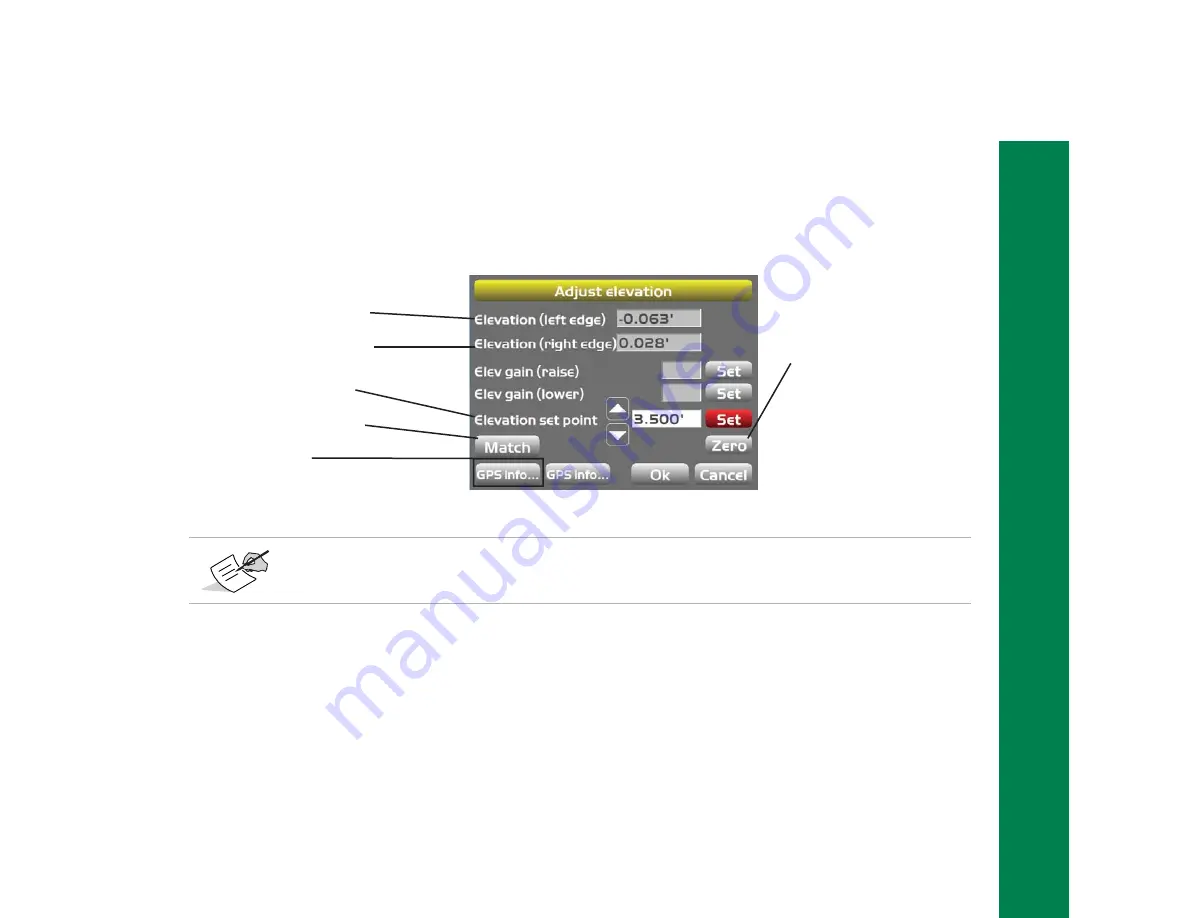
Adjust Elevation
Figure
11:
Adjust
Elevation
Screen
ŝƐƉůĂLJƐƚŚĞĞůĞǀĂƟŽŶŽĨ
ƚŚĞďůĂĚĞ͛ƐůĞŌĞĚŐĞ͘
ŝƐƉůĂLJƐƚŚĞĞůĞǀĂƟŽŶŽĨ
ƚŚĞďůĂĚĞ͛ƐƌŝŐŚƚĞĚŐĞ͘
ŝƐƉůĂLJƐƚŚĞĐƵƌƌĞŶƚ
ĐƵƚͬĮůůŽīƐĞƚ͘
^ĞƚƐƚŚĞĐƵƌƌĞŶƚĚĞƐŝŐŶƐƵƌĨĂĐĞƚŽ
ƚŚĞĐƵƫŶŐĞĚŐĞĞůĞǀĂƟŽŶ͘
Sets the
ůĞǀĂƟŽŶƐĞƚƉŽŝŶƚ
ǀĂůƵĞƚŽnjĞƌŽ͘
Displays the
'W^ŝŶĨŽƌŵĂƟŽŶ
ĚŝĂůŽŐďŽdž͘
MC
‐
i3
units
with
either
FH915+
or
Digital
UHF2
will
not
have
the
second
GPS
info...
button.


