background image

Entering Sensor Information  

 3-7

P/N: 7010-1006

Machine Setup and Configuration

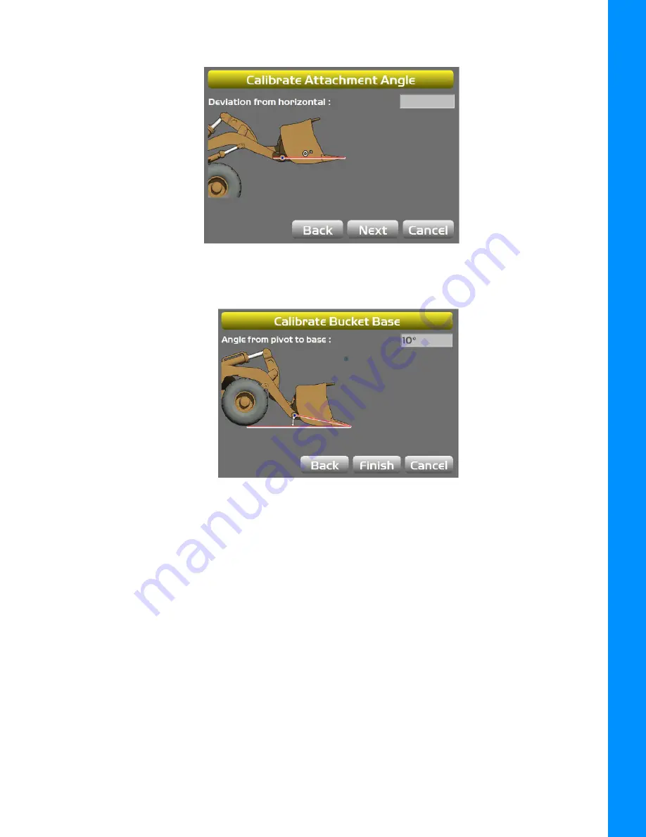
b. Press 

Next

 to access the 

Calibrate Attachment Angle

 screen (Figure 3-9).

Figure 3-9: Calibrate Attachment Angle

c. Press 

Next

—the 

Calibrate Bucket Base

 screen populates (Figure 3-10).

Figure 3-10: Calibrate Bucket Base

d. Press 

Finish

 on the 

Calibrate Bucket Base

 screen—to return to the 

WheelLoader Bucket 

Setup 

screen (Figure 3-11).

Summary of Contents for 3D-MC

Page 1: ...n and Calibration Manual For more information contact Synergy Positioning Systems or visit the Synergy Positioning Systems website at www synergypositioning co nz All branches Phone 0800 867 266 Email...

Page 2: ......

Page 3: ...pyright Topcon Positioning Systems Inc August 2018 Topcon Positioning Systems Inc All rights reserved The information contained herein may not be used accessed copied stored displayed sold modified pu...

Page 4: ...Sensor Installation 2 4 Boom Sensor Installation 2 5 Body Sensor Installation 2 6 GNSS Antenna Mount and Mast Installation 2 7 Machine Setup and Configuration 3 1 Entering Sensor Information 3 1 Taki...

Page 5: ...by TPS Trademarks Topcon Topcon Positioning Systems 3D MC are trademarks or registered trademarks of TPS GX 55 GX 75 MC i4 TS i3 are trademarks of TPS Windows is a registered trademark of Microsoft C...

Page 6: ...rietary information of TPS You agree to treat TPS Confidential Information with a degree of care no less stringent that the degree of care you would use in safeguarding your own most valuable trade se...

Page 7: ...another manual or help document Refer to the Topcon Reference Manual Further information to note about system configuration maintenance or setup Supplementary information that can have an adverse affe...

Page 8: ...the Wheel Loader s body boom and bucket This information is sent to the GX 55 GX 75 Control Box to provide precise 3D guidance Each sensor is configured and calibrated for its specific location on the...

Page 9: ...ller Receiver GPS Antennas GPS Antenna 2 GX 60 GX 55 GX 75 Control Box Body Sensor Boom Sensor Mounted Inside Boom Attachment Bucket Sensor Mounted Inside Snap on Well The TS i3 Boom Sensor is mounted...

Page 10: ...2 Figure 1 2 Basic Cable Connections Figure 1 3 shows the basic cabling connections for the Wheel Loader system When installing hardware components use the Topcon supplied fuse or fused power from the...

Page 11: ...ng measured See Figure 2 1 below Locate surfaces that protect the sensor from physical damage and are convenient for cable routing When the position of the implement is at zero degrees horizontal make...

Page 12: ...escending order When entering sensor information make note of each sensor s serial number and its orientation TS i3 sensor orientation for Boom and Bucket also known as the Attachment sensor is only l...

Page 13: ...lease Attachment Bucket Sensor Installation The recommended location for the TS i3 Attachment Bucket Sensor is on the inside of the Bucket Snap on Well Figure 2 2 Recommended Placement of TS i3 Attach...

Page 14: ...or Installation When using a Quick Release Wheel Loader Bucket Assembly the recommended mounting location for the TS i3 sensor is as shown in Figure 2 3 Figure 2 3 Mounting Location for TS i3 Sensor W...

Page 15: ...N 7010 1006 Installation Boom Sensor Installation Weld or bolt the TS i3 Boom sensor onto the inside of the Boom with the with the arrow facing forward in the direction of travel Figure 2 4 Boom Senso...

Page 16: ...d sensor to the front frame of the Wheel Loader Ensure that the sensor is squared to the Wheel Loader Weld or bolt the Body Sensor so that the sensor is flat Figure 2 5 Body Sensor Wheel Loader Instal...

Page 17: ...l Loader Figure 2 6 Antenna Mast and Mast Weld Mount 3 Install the Antenna Mast 4 Install the Strain Relief Bracket Remove the two small Bolts and route the GNSS Antenna Cable through the Strain Relie...

Page 18: ...t steps 3 and 4 for the second antenna mast Ensure enough cable is routed through the bracket so that the cable can be looped over and threaded into the bracket if or when the antenna is removed from...

Page 19: ...9 P N 7010 1006 Installation 6 Install the two GNSS antennae Figure 2 8 GNSS Antenna Mast Weld Mounts and Front Lamp Protection Plate Installed on the Wheel Loader Antenna Mast Weld Mount 2 Antenna Ma...

Page 20: ...sor s serial number ending in 00 is considered a special CAN identifier and will be identified as 01 in 3D MC software Therefore if you have a sensor with 00 and a sensor with 01 there will be some co...

Page 21: ...GNSS GNSS Aux Body and Boom Machine Measurements Record Wheel Loader Information below Record Wheel Loader Information below Make a copy of this page Use this page to record the GNSS Wheel Loader Ante...

Page 22: ...6 Machine Setup and Configuration Figure 3 2 Bucket and Tilt Bucket Measurements Record Wheel Loader Information below Make a copy of this page Use this page to record Wheel Loader Bucket and Tilt Buc...

Page 23: ...e sensor s serial number the physical orientation of the sensor mounting Step 1 Configure the Machine File and the Wheel Loader options 1 In 3D MC tap Topcon Menu Button Control Machine setup 2 Select...

Page 24: ...ut Figure 3 4 7 Tap Next to navigate to the Wheel Loader Antenna screen and select enter the appropriate values as needed Figure 3 5 Wheel Loader Antenna 8 Tap Next to navigate to the Wheel Loader Ant...

Page 25: ...ne element that you are working on 3 Enter the appropriate measurement values 4 Tap Next on the Loader Frame Sensors screen Figure 3 7 the WheelLoader Bucket Setup screen appears Figure 3 8 Figure 3 8...

Page 26: ...the Calibrate Attachment Angle screen Figure 3 9 Figure 3 9 Calibrate Attachment Angle c Press Next the Calibrate Bucket Base screen populates Figure 3 10 Figure 3 10 Calibrate Bucket Base d Press Fin...

Page 27: ...1006 Machine Setup and Configuration Figure 3 11 WheelLoader Bucket Setup f Repeat Steps 4a through 4d for each attachment Information regarding body boom and attachment bucket sensor calibration rou...

Page 28: ...and Configuration Light Bars 1 Tap Next to access the Light Bars screen Figure 3 12 Light Bars 2 Enter the desired settings Machine Configuration Complete Tap Next to access the Configuration complete...

Page 29: ...priate machine file and tap Edit 3 Continue to press Next to access the Loader Frame Sensors screen Figure 4 1 4 Tap the Wrench icon for the Body sensor Figure 4 1 5 Tap the Orientation box and select...

Page 30: ...ng the Roll value 8 Mark the position on the four wheels on the ground 9 Move the Wheel Loader around 180 degrees so that the tires are repositioned on the same ground marks 10 Tap Set next to Pitch s...

Page 31: ...ser height to strike the center of the Boom Pivot 6 Move the Boom to align the Bucket Pivot with the laser 7 Tap the Wrench Icon that corresponds to the Boom sensor Figure 4 3 Boom Sensor Calibration...

Page 32: ...the Wheel Loader is parked on a flat and stable surface 4 Place a zero slope rotating laser along the side of the Wheel Loader 5 Adjust the laser height to strike the center of the Bucket Pivot 6 Rota...

Page 33: ...screen Attachment Bucket Edge Sensor Calibration Perform the following Attachment Bucket Edge Calibration Sensor procedure for all attachments 1 In 3D MC Software Interface application tap Topcon Men...

Page 34: ...r Filtering The filter level for each sensor can be changed depending on the application and the operator s choice A value of 4 heavy filtering will dampen sensor reaction while a value of 1 light fil...

Page 35: ...7010 1006 Calibration 4 Select a Filtering level and tap Ok Figure 4 9 Figure 4 9 Sensor Filtering 5 Navigate through the remaining steps of Machine Setup then save the file and exit the 3D MC Softwar...

Page 36: ...ility of the operator 5 Use cable ties supplied with the Wheel Loader system to keep hoses and wires secured and away from possible wear or pinch points 6 Use eye protection whenever welding cutting o...

Page 37: ...nsure that surveyors did not interfere with voice users The solution was to stop using frequencies in the 469 MHz range to add an identifier to the broadcast message and other measures designed to min...

Page 38: ...dropped altered transported or shipped without proper packaging or otherwise treated without care erroneous measurements may occur The owner should periodically test this product to ensure it provides...

Page 39: ...Specifications subject to change without notice All rights reserved 7010 1006 Revision B 8 2018 2018 Topcon Corporatiion www topconpositioning com...

Reviews:

Related manuals for 3D-MC