5
RUDDER ASSEMBLY
£
1 The rudder core sheet (RC) has a ply trailing edge (RTE) similar to the elevator core sheets. Assemble
the rudder core sheet.
£
12 Cut two hinges in half lengthwise to produce four
1” x 3/8” hinges. Install these to the elevators and
stabilizer at the locations indicated on the plans.
Do not glue until after covering. This concludes
the stabilizer/elevator assembly.
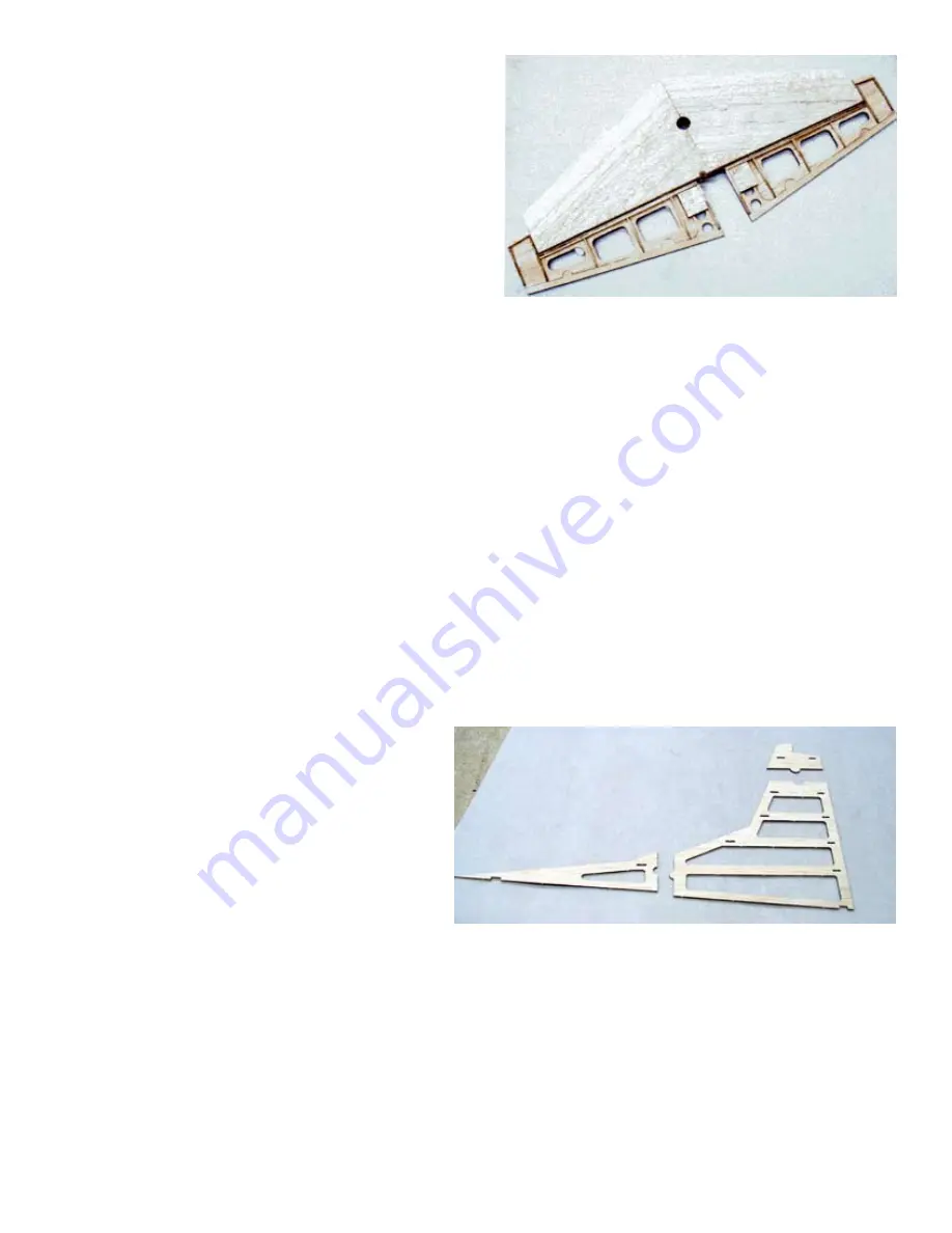
RIGHT
The completed stabilizer and elevator assembly ready for cov eting
and then installation on to the fuselage assembly. Assure that the
hinges work freely and that the elevator counterbal ance protrusions
do not bind, allow for covering material.
£
2 Install R1 through R6.
£
3 Install the rudder leading edge RLE. Install R8 and R9.
£
4 Install the rudder horn caps RHC.
£
5
Sand or plane a 20° angle on the rudder leading edge for hinge clearance.
£
6
Cut a 5/8” length of 1/8” brass tube. Crush flat about 3/16” at both ends. Drill a 1/16” hole in both ends
about 3/32” from the end. Bend the 1/16” M.W. rudder torque rod and slide the one end of the brass tube
onto the end of the torque rod. Solder in position at 90° to the bend. Do not install permanently in the
rudder until after covering.
VERTICAL FIN ASSEMBLY
£
1
Assemble the three fin core sheet sections.
Use the same technique as you did on the
stabilizer core sheet assembly.
£
2 Install ribs V-1 through V6. Use a straight
edge to assure that V-1 is straight and at
90° to the core sheet. This will provide the
platform of the fin that will attach to the
fuselage top and must be flat.
Like the stabilizer and elevator assembles, the vertical fin is built on a core sheet. Shown
here are the three sections of the vertical fin core sheet ready to be assembled.


