


MAINTENANCE AND TROUBLESHOOTING
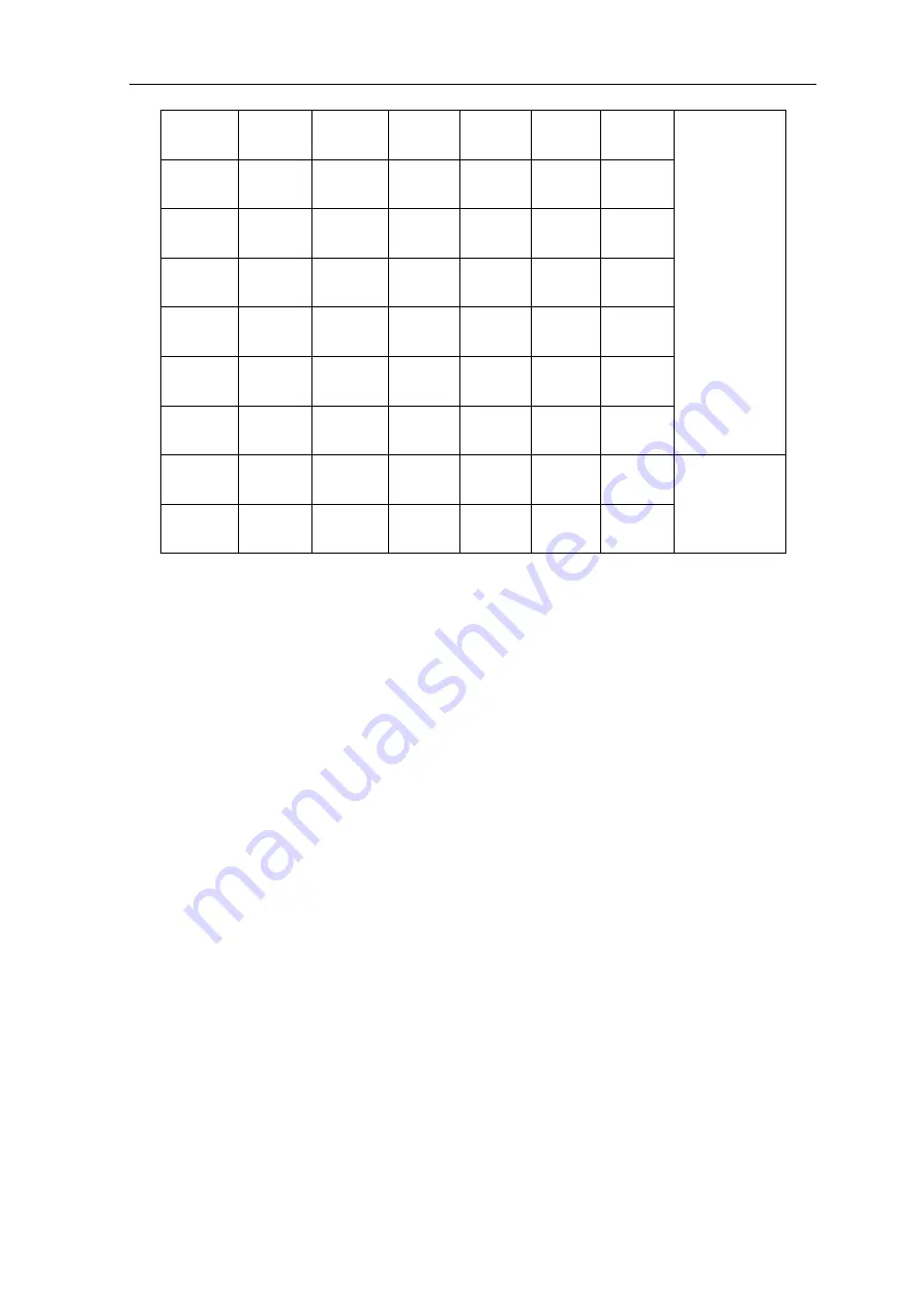
26
8
4
~
5
5
100
260
~
320
16
~
20
14
~
16
10
4
~
5
5
100
~
150
280
~
340
16
~
20
14
~
16
12
4
~
5
5
~
6
150
~
200
300
~
360
18
~
22
16
~
20
14
5
~
6
5
~
6
180
~
200
340
~
380
20
~
24
16
~
20
16
5
~
6
6
200
~
220
340
~
380
20
~
24
16
~
20
18
5
~
6
6
200
~
240
360
~
400
25
~
30
16
~
20
20
5
~
6
6
200
~
260
360
~
400
25
~
30
20
~
22
16
~
20
5
~
6
6
200
~
260
300
~
380
25
~
30
16
~
20
X-groove butt
welding
22
~
25
5
~
6
6
~
7
200
~
260
360
~
400
30
~
35
20
~
22
Notice: the above parameters originate from
《
Welding Dictionary
》
P538, Volume 2 of Edition 2.
§4.6 Operation Environment
●
Height above sea level is below 1000m.
●
Operation temperature range:-10
0
C
~
+40
0
C.
●
Relative humidity is below 90 % (20
0
C).
●
Preferably site the machine some angles above the floor level, the maximum angle does not exceed
15
0
.
●
Protect the machine against heavy rain or in hot circumstance against direct sunshine.
●
The content of dust, acid, corrosive gas in the surrounding air or substance can not exceed normal
standard.
●
Take care that there is sufficient ventilation during welding. There is at least 30cm free distance
between the machine and wall.


