23
❏
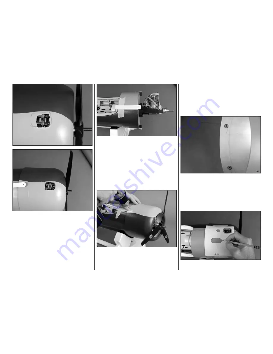
3. Remove the cowl. Use a rotary tool with a carbide
cutter to cut the hole, but keep the cut undersize so it
can be enlarged and shaped as you proceed and “zero-
in” on the fi nal shape. Replace the cowl and propeller
to see if the cutout is large enough and positioned to
clear the engine. Continue to mark and cut the cowl
as necessary until the cutout is just large enough so
the cowl will fi t over the engine.
NOTE:
As you proceed
be certain to use compressed air to blow dust off the
cowl so it does not get into the engine.
❏
4. Make four cowl screw templates from thin
cardstock. Tape the templates to the fuselage with
the hole in the templates centered over the middle of
each cowl mount block indicating where to drill.
❏
5. Once the cowl fi ts over the engine, center the
cowl on the engine crank shaft aligning the paint lines
on the cowl with the covering lines on the fuselage.
Rotate the propeller to make sure you have adequate
clearance all the way around the cowl. View the cowl
and fuselage from all angles, making sure the cowl is
positioned precisely how you want it.
❏
6. Using one of the templates as a guide, drill a 3/32"
[2.4mm] hole through the cowl into the mount block.
Remove the cowl. Enlarge the hole
in the cowl only
with a 1/8" [3.2mm] drill. Replace the cowl and propeller.
Mount the cowl with a #2 × 5/8" [16mm] Phillips screw.
❏
7. Realign the cowl and repeat the process of drilling
the hole, removing the cowl, enlarging the hole in the
cowl only and remounting the cowl with another screw
until all four holes have been drilled and the cowl is
mounted.
Caution:
Don’t forget to replace the 1/8" drill
with the 3/32" drill before drilling each hole through
the cowl and mount blocks!
❏
8. Use medium CA to glue the 1/32" [.8mm] plywood
cowl mounting
screw hole doublers
to the inside of
the cowl centered on each hole. Remove the balsa
spacers from the cowl mounting blocks.
Now that the cowl is mounted, the cutout for the engine
needs to be fi nished and the rest of the holes for the
muffl er, needle valve, fueling, etc. also have to be cut.
❏
9. If you’ve mounted the O.S. FS91 as shown in the
manual, you can use the template for marking and
Summary of Contents for Giant F4U Corsair
Page 32: ...32 32 Components in Fuselage Components in Wing...
Page 34: ...34 34...
Page 35: ...35 Cowl Hole Template For O S 91 4 stroke...
Page 36: ...Cowl Hole Template For O S 95V...


