

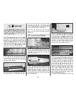


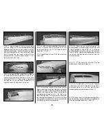


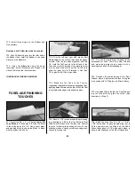


Remove the hull (I meant to say fuselage) from
the building board, and install the landing gear
with six 8-32 x 1/2” socket head cap screws. The
landing gear struts provide a built-in stand to
help avoid hangar rash on the underside. Looks
pretty sleek, huh?
SPECIAL BUILDER’S NOTE:
As this model has
been designed with the scale builder in mind, the
servos, receiver, battery and tank are all hidden
under the instrument panel so they are less
conspicuous and leave the cabin interior open for
unlimited detailing. Because of this location you
will find it much easier to install these components
before the top of the fuse is assembled. We are
not saying that they can’t be installed (or
removed) later, it’s just
much easier to do it now.
❏
Before assembling the fuse top, fuel proof and
paint the interior from F-1 to F-2 including the
servo tray. We used K & B Black Super Poxy paint
with satin catalyst to do both jobs at one time.
❏
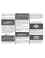
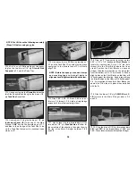
1. Locate the two .074” x 36”
Pushrod Wires
.
Cut six or seven 1/4” long bushings of inner
pushrod tube, then slide these along the wire
from the unthreaded end. Space them out evenly
but make sure that the bushings on the ends are
at least 4” from the end of the wire. If the
bushings slide too easily, use a small drop of thin
CA to hold them in position. Slide a silicone
Retainer
onto the rear of a nylon
Clevis
, then
screw the Clevis onto the Pushrod about 14 turns.
Make a second Pushrod in the same manner.
❏
2. Make sure that the CA on the bushings has
thoroughly cured
(
you don’t want the Pushrods
glued to the inside of the tubes) then insert the
Pushrod wires over the top of F-1 into the
forward
end of the Pushrod Tubes and slide
them all the way through.
❏
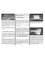
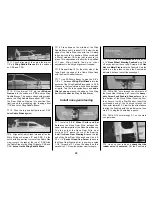
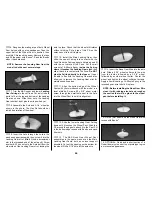
3. Cut the
Rudder Servo Horn pattern
from
the plans and glue it to a large servo wheel with
rubber cement. Cut out the custom horn shape
with a razor saw and grinding wheel. Drill the
clevis holes with a 1/16” bit.
❏
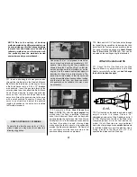
4. Install three servos as shown with their
splined shafts toward F-1.
Depending on
engine choice (2-stroke or 4-stroke), the throttle
servo location can be on either the left or the
right side of the servo tray. The receiver
switch
can also be installed in the servo tray at this
time, or you could mount it through the fuse
sheeting during final assembly.
❏
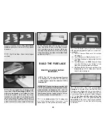
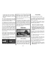
1. Drill four 15/64” diameter holes through the
laminated Firewall for the engine mounting bolts at
the marked locations. Insert four 8-32 blind nuts
into the holes from the aft side (that’s the side with
the lightening hole) and seat them with gentle taps
from a hammer. Wick a little thin CA around the
edge of each nut to secure it in position.
Frame fuselage top
Install pushrods and servos
Fuelproof and paint the interior
33
Summary of Contents for CESSNA 182 SKYLANE
Page 8: ...8 DIE CUT PATTERNS ...


