background image

Installation and Maintenance Tips

Following the guidelines will help you to ensure the pneumatic tools your company uses are operating and are 

maintained in the very best of condition.

Initial Inspection of a New Tool 

When a new tool is delivered to your facility, it is important to inspect the tool for any signs of damage that may 

have occurred during shipping. Here is a list of things to inspect:

● With the tool disconnected from the air supply, depress the throttle lever or trigger. The device should move 

freely and not become caught.

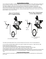
● Inspect the guard of the tool, if so equipped. The guard should be free of any chips, nicks or dents. 

● Inspect the output of the tool. The threads should show no signs of bends or chips. Grasp the spindle by 

hand and spin. The spindle should turn freely with no resistance. 

Plumbing Installation

The tool must have fittings and connectors installed into the air inlet in order to connect with your companies 

air system. Your choice of fittings can greatly affect the performance of the tool. 

Fitting Size

The size of the air inlet of the tool is the minimum size of fitting that will allow for proper airflow into the tool. 

Should a smaller fitting size be used such as reducers or adapters, this will constrict the airflow into the tool 

and reduce the overall performance. 

Coupling Size and Installation

The coupling size should be equal to or larger than the inlet size of the tool. If a smaller size coupling is used 

then the air supply volume may be reduced which may lead to reduced performance from the tool. 

The coupling should be installed near to the tool. It is important that the tool receive internal lubrication on a 

regular basis. Having the connection closer to the tool will promote regular lubrication, as the connection is 

easily accessible. Hose whips are often used between the tool and the coupling.

Use thread sealant on all pipe threads and ensure a tight fit.

Operating Speed Test

After your initial inspection and installation of the plumbing connections, it is important to test for the operating 

speed of the tool. This test should be performed before you install any abrasive or tooling. Each tool is 

stamped with a maximum operating speed. This speed determines the highest rotational speed in R.P.M.’s 

that the tool will turn when it is functioning properly. This speed was set from the factory and is closely related 

to the operating speed of the abrasive used with the tool. This relationship will be discussed in the “mounting 

abrasives and blades” section. 

Find the maximum operating speed stamped onto the tool. Connect the tool to an air supply that provides 

90 psi and secure the tool in a vise. A lower or higher air pressure will result in a false speed test and may 

create a hazardous situation. Depress the throttle lever or trigger and run the tool. Use a properly calibrated 

tachometer to determine the actual operating speed of the tool. The actual operating speed on the tachometer 

should be 90-95% of the maximum free speed stamped on the tool. If this is not the case then contact the 

distributor or tool manufacturer immediately. The tool must not be put into service if the actual speed is over 

95% of the stamped maximum speed. 

Example: Tool rated at 6000 R.P.M. 


     90% of 6000 (.90 x 6000) = 5400


     95% of 6000 (.95 x 6000) = 5700

The tool should run between 5400 R.P.M. and 5700 R.P.M. when tested with a tachometer. Tachometers must 

be checked and calibrated on a regular basis according to the manufacturers recommendations

Summary of Contents for 65VBW-9" Guard

Page 1: ...tcservice com Read Safety Recommendations Before Operating Tool Model Number Power Output Rated Speed Weight Blade Diameter Maximum Depth of Cut Arbor Hole Size Working Air Consumption 65VBW 9 Guard 4 H P 3000 KW 4000 6000 R P M 26 3 Lb 11 9 Kg 9 Inch 230 mm 2 5 Inches 64 mm 5 8 Inch 16 mm 50 cfm 23 6 L S 65VBW 12 Guard 28 3 Lb 12 8 Kg 12 Inch 300 mm 3 5 Inches 89 mm 1 0 Inch 25 mm 65VBW 14 Guard ...

Page 2: ...nd that it is properly mounted to the tool Any guard showing signs of wear such as bends chips nicks or cracks should be replaced Check hose size and air pressure The air pressure at the tool shall not exceed 90 psi 6 2 bar All hoses should be inspected regularly and kept away from heat oil and sharp edges Be sure the tool is secured to the air hose Measure the speed of grinders every 20 hours of ...

Page 3: ...not create a hazard to the eyes or will ignite the environment 7 Grinders and saws shall not be used in potentially explosive atmospheres 8 Pneumatically driven tools are not generally insulated from coming in contact with electrical sources Be sure to avoid contact with wires or other possible current carrying sources 9 The operator must check that no bystanders are in the vicinity 10 Remember th...

Page 4: ...ey of spindle and slide spindle assembly through Remove wheel flange 550 12B Remove from vise Remove key 700 15 and lift off front end plate 700 10 12 On 12 and 14 guard models remove snap ring 591132 using snap ring pliers 14 Support front bearing assembly on a suitable drill block Press spindle through front bearing 700 9 with arbor press 15 Remove snap ring 550 21 using snap ring pliers Lift out...

Page 5: ... a wrench left hand thread 19 Assemble spade handle if this was inspected or repaired 20 Install spade and dead handles to case 660 1 S 21 Secure tool in a vise with motor axis in horizontal position Clap onto thespade handle 22 Place gasket 650 13 in rear face of case 23 Slide the motor assembly into case The motor assembly must be kept straight to install into the case easily Try to maintain ali...

Page 6: ...ER 3 REQ 700 47A SCREW 3 REQ 700 48 SCREW 2 REQ 700 54 LOCK WASHER 2 REQ 1000 5 LOCK RING 591132 SNAP RING GUARDS PART NUMBER DESCRIPTION 650 SV 9 9 SAW GUARD 650 S 102 12 SAW GUARD 650 S 104 14 SAW GUARD TOOLS PART NUMBER DESCRIPTION 1100 94 15 16 WRENCH 1100 150 1 1 2 WRENCH 1100 200 2 WRENCH 1100 650 SPINDLE HOLDER 1100 808 700 9 BEARING DRIVER 1100 834 700 7 BEARING DRIVER 541228 2 X 12 LONG W...

Page 7: ...CREW 700 30 O RING 700 48 SCREW 2 REQ 700 54 LOCK WASHER 2 REQ 700 S 20 THROTTLE LEVER 700 S 26 THROTTLE VALVE CAP 832636 GASKET 841555 1 2 NPT X 1 2 NPT SCREEN HANDLE BUSHING 841555 M 1 2 NPT X 1 2 BSP SCREEN HANDLE BUSHING Note Use of any parts other then genuine Top Cat parts voids any and all warranties and may result in a hazardous situation and a decrease in operating efficiency ...

Page 8: ...ns that require the wrist to be flexed hyper extended or turned side to side 4 Avoid anything that may inhibit blood circulation such as smoking tobacco or cold temperatures 5 Do not support body weight on the tool during operation 6 Maintain a stress free posture for the entire body Prolonged exposure to vibrations created by vibrating sources may cause health hazards There are gloves handle wraps...

Page 9: ...rnal lubrication on a regular basis Having the connection closer to the tool will promote regular lubrication as the connection is easily accessible Hose whips are often used between the tool and the coupling Use thread sealant on all pipe threads and ensure a tight fit Operating Speed Test After your initial inspection and installation of the plumbing connections it is important to test for the op...

Page 10: ...d be aware of when mounting abrasives The maximum operating speed marked on the wheel or blade must be equal to or higher than the rated spindle speed free speed of the tool Check the wheel or blade dimensions so that it fits within the guard properly Do not use any wheel that shows cracks chips or evidence it has been soaked in fluids Wheel flanges should have flat contact surfaces and be without cra...

Page 11: ...supply It is important to inspect both the setting and amount of oil in the lubricator regularly to determine proper functioning of the device The lack of oil in the air system will greatly reduce the performance and longevity of the pneumatically driven tool 2 Direct injection of oil into the tool A simple and easy way to ensure proper lubrication is to inject the oil directly into the tool air i...

Page 12: ... contact with the endplates Some wear can be seen on both the top and bottom surfaces of the overall length Should the overall length wear to the minimum length of 1 993 inches then the rotor should be replaced The Cylinder 700 11 The only wear seen on the cylinder is going to occur on the inner surface This surface is always in contact with the blades Over time the blades will remove material fro...

Reviews: