background image

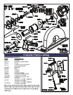
the air system and become lodged onto the blades. This can cause the blades to delaminate where pieces of 

blade material will flake off. Any blade exhibiting this characteristic should be replaced. The blades will see the 

most wear on the longest edge along their height. This is the surface that makes contact with the cylinder wall 

and creates an air seal. The overall width of the blade will reduce as this surface wears. When any one-end 

width of the blade wears to the minimum width, (.347 inches) then one should consider replacement. 

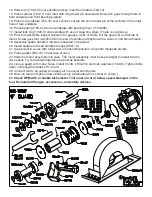
The Bearings (700-7 and 700-9). There is no means of measurement that can determine the condition of a 

bearing. The only test that can be performed it to manually turn either the outer of inner race with respect 

to each other. The movement should feel free with no resistance. If resistance is felt either continuous or 

repetitive, then the bearing should be replaced

The Front Endplate (700-10). The front endplate is essentially a flat steel disc in the front of the motor 

assembly. The rotor makes occasional contact with the front endplate. Over time, this contact will wear away 

the surface of the endplate and result in a circular depression in the middle of the part. When this depression 

becomes 0.003 inches deep from the original surface, then the efficiency of the motor is reduced to the point 

where one should replace the endplate. * Note – The front endplates are designed so either front or back 

surface can be used toward the motor. When one side is judged as unusable, the part can be flipped during 

reassembly and new wear surface is available.    

The Rotor (700-12). We employ a floating rotor design in the many of our motors. This design allows the rotor 

to float along the spindle in the motor cavity. Occasionally the rotor will make contact with the endplates. Some 

wear can be seen on both the top and bottom surfaces of the overall length. Should the overall length wear to 

the minimum length of 1.993 inches then the rotor should be replaced. 

The Cylinder (700-11). The only wear seen on the cylinder is going to occur on the inner surface. This surface 

is always in contact with the blades. Over time, the blades will remove material from this surface that will 

reduce the overall performance of the tool. Consecutive high and low spots will become evident on the internal 

surface. They will appear as ridges along the axis of the cylinder. When these ridges vary 0.016 inches from 

high to low, the cylinder should be replaced.   

The Rear Endplate (700-16). The rear endplate is the located toward the rear of the motor assembly. The most 

wear this part is exposed to is from occasional contact with the rotor. Over time, this contact will wear away 

the surface of the endplate and result in a circular depression in the middle of the part. When this depression 

becomes 0.003 inches deep from the original surface, then the efficiency of the motor is reduced to the point 

where one should replace the endplate. 

This covers all of the predictable wear that can occur within the tool. Other factors due to environment, level of 

treatment/care and air supply quality can cause other forms of wear that are unpredictable.

For More Information

1) General Industry Safety & Health Regulations 29 CFR, Part 1910 and where applicable Construction 

Industry Safety & Health Regulations 29 CFR, Part 1926 available from Superintendent of Documents, Gov’t. 

Printing Office, Washington, D.C. 20402.

2) Safety Code For Portable Air Tools, ANSI B186.1, B7.1 and Z87.1, available from American National 

Standards Institute, Inc. 1430 Broadway, New York, NY 10018

© Copyright 2005

All Rights Reserved

T.C. Service Co.

38285 Pelton Rd.

Willoughby, OH 44094

U.S.A.

Ph: 440-954-7500

Fax: 440-954-7118

Saws

Air Motors

Drills

Grinders

Percussion Tools

Polishers

Summary of Contents for 65VBW-9" Guard

Page 1: ...tcservice com Read Safety Recommendations Before Operating Tool Model Number Power Output Rated Speed Weight Blade Diameter Maximum Depth of Cut Arbor Hole Size Working Air Consumption 65VBW 9 Guard 4 H P 3000 KW 4000 6000 R P M 26 3 Lb 11 9 Kg 9 Inch 230 mm 2 5 Inches 64 mm 5 8 Inch 16 mm 50 cfm 23 6 L S 65VBW 12 Guard 28 3 Lb 12 8 Kg 12 Inch 300 mm 3 5 Inches 89 mm 1 0 Inch 25 mm 65VBW 14 Guard ...

Page 2: ...nd that it is properly mounted to the tool Any guard showing signs of wear such as bends chips nicks or cracks should be replaced Check hose size and air pressure The air pressure at the tool shall not exceed 90 psi 6 2 bar All hoses should be inspected regularly and kept away from heat oil and sharp edges Be sure the tool is secured to the air hose Measure the speed of grinders every 20 hours of ...

Page 3: ...not create a hazard to the eyes or will ignite the environment 7 Grinders and saws shall not be used in potentially explosive atmospheres 8 Pneumatically driven tools are not generally insulated from coming in contact with electrical sources Be sure to avoid contact with wires or other possible current carrying sources 9 The operator must check that no bystanders are in the vicinity 10 Remember th...

Page 4: ...ey of spindle and slide spindle assembly through Remove wheel flange 550 12B Remove from vise Remove key 700 15 and lift off front end plate 700 10 12 On 12 and 14 guard models remove snap ring 591132 using snap ring pliers 14 Support front bearing assembly on a suitable drill block Press spindle through front bearing 700 9 with arbor press 15 Remove snap ring 550 21 using snap ring pliers Lift out...

Page 5: ... a wrench left hand thread 19 Assemble spade handle if this was inspected or repaired 20 Install spade and dead handles to case 660 1 S 21 Secure tool in a vise with motor axis in horizontal position Clap onto thespade handle 22 Place gasket 650 13 in rear face of case 23 Slide the motor assembly into case The motor assembly must be kept straight to install into the case easily Try to maintain ali...

Page 6: ...ER 3 REQ 700 47A SCREW 3 REQ 700 48 SCREW 2 REQ 700 54 LOCK WASHER 2 REQ 1000 5 LOCK RING 591132 SNAP RING GUARDS PART NUMBER DESCRIPTION 650 SV 9 9 SAW GUARD 650 S 102 12 SAW GUARD 650 S 104 14 SAW GUARD TOOLS PART NUMBER DESCRIPTION 1100 94 15 16 WRENCH 1100 150 1 1 2 WRENCH 1100 200 2 WRENCH 1100 650 SPINDLE HOLDER 1100 808 700 9 BEARING DRIVER 1100 834 700 7 BEARING DRIVER 541228 2 X 12 LONG W...

Page 7: ...CREW 700 30 O RING 700 48 SCREW 2 REQ 700 54 LOCK WASHER 2 REQ 700 S 20 THROTTLE LEVER 700 S 26 THROTTLE VALVE CAP 832636 GASKET 841555 1 2 NPT X 1 2 NPT SCREEN HANDLE BUSHING 841555 M 1 2 NPT X 1 2 BSP SCREEN HANDLE BUSHING Note Use of any parts other then genuine Top Cat parts voids any and all warranties and may result in a hazardous situation and a decrease in operating efficiency ...

Page 8: ...ns that require the wrist to be flexed hyper extended or turned side to side 4 Avoid anything that may inhibit blood circulation such as smoking tobacco or cold temperatures 5 Do not support body weight on the tool during operation 6 Maintain a stress free posture for the entire body Prolonged exposure to vibrations created by vibrating sources may cause health hazards There are gloves handle wraps...

Page 9: ...rnal lubrication on a regular basis Having the connection closer to the tool will promote regular lubrication as the connection is easily accessible Hose whips are often used between the tool and the coupling Use thread sealant on all pipe threads and ensure a tight fit Operating Speed Test After your initial inspection and installation of the plumbing connections it is important to test for the op...

Page 10: ...d be aware of when mounting abrasives The maximum operating speed marked on the wheel or blade must be equal to or higher than the rated spindle speed free speed of the tool Check the wheel or blade dimensions so that it fits within the guard properly Do not use any wheel that shows cracks chips or evidence it has been soaked in fluids Wheel flanges should have flat contact surfaces and be without cra...

Page 11: ...supply It is important to inspect both the setting and amount of oil in the lubricator regularly to determine proper functioning of the device The lack of oil in the air system will greatly reduce the performance and longevity of the pneumatically driven tool 2 Direct injection of oil into the tool A simple and easy way to ensure proper lubrication is to inject the oil directly into the tool air i...

Page 12: ... contact with the endplates Some wear can be seen on both the top and bottom surfaces of the overall length Should the overall length wear to the minimum length of 1 993 inches then the rotor should be replaced The Cylinder 700 11 The only wear seen on the cylinder is going to occur on the inner surface This surface is always in contact with the blades Over time the blades will remove material fro...

Reviews: