background image

22 

MAINTENANCE & CARE 

General cleaning will help prolong the life and performance of your treadmill. Keep the unit 
clean and maintained by dusting the components on a regular basis. Clean both sides of 
the running belt to prevent dust from accumulating underneath the belt. Keep your running 
shoes clean so that dirt from your shoes does not wear out the running board and belt. 
Clean the surface of the running belt with a clean damp cloth.


To better maintain the treadmill and prolong its life it is suggested that the machine be
powered off for 10 minutes every 2 hours and fully powered off whenever not in use.

A loose Running Belt will result in the runner sliding off when running, while too tight of a
Running  Belt  will  result  in  decrease  to  the  motors  performance  and  also  create  more
friction between the roller and running belts. The most suitable tightness for the belts is
pulled out 50-75mm from the Running Board.

CENTERING THE RUNNING BELT: 

Place the treadmill on level ground and set it at 6-8kph to check if the Running Belt drifts. 

1. If the 

Running Belt

 moves to the 

right

,

turn the adjusting bolt on the right side 

¼

turn 

clockwise

,  then  turn  the  left

adjustment bolt ¼ turn 

counter-clockwise

.

If the belt does not move, repeat this step
until it centers.    Refer to figure    A.

2. If the 

Running Belt

 moves to the 

left

,

turn the adjusting bolts on the left side 

¼

of  a  turn 

clockwise

,  then  turn  the  right

adjustment bolt ¼ turn 

counter-clockwise

.

If the belt does not move, repeat this step
until it centers.    Refer to figure B.

3.


Over time the 

Running Belt 

will


loosen

. To tighten the belt turn the Left &


Right side adjustment bolts one full turn


clo


ckwis


e, check the tension of the belt.


Continue this process until belt is at the


correct tension. Make sure to adjust both


sides  equally  to  ensure  correct  belt


alignment. Refer to figure C.


Summary of Contents for MIRAGE C60

Page 1: ...Ed Rev Cod INSTRUCTION 03 21 GRLDTOORXTRXMC6 00 ...

Page 2: ...3 NO DES Specification Nos NO DES Specification Nos A Main frame 1 C55 Silicone oil 1 B09 6 Allen wrench 1 D09 Power wire 1 C39 Safety key set 1 ...

Page 3: ...4 ...

Page 4: ...5 ...

Page 5: ...6 ...

Page 6: ...7 ...

Page 7: ...8 ...

Page 8: ...9 ...

Page 9: ...10 ...

Page 10: ...11 ...

Page 11: ...12 LATERAL FOLDING ...

Page 12: ...13 ...

Page 13: ...14 VERTICAL FOLDING ...

Page 14: ...15 ...

Page 15: ...16 ...

Page 16: ... then short press to start the machine or long press to go back to standby mold Under manual mode press the knob button the treadmill will be started after 3seconds countdown Under pause mode quick press this knob button to re start the machine Under pause mode long press this knob button for 3 seconds the machine will be stop and reset Under standby mode turn the knob clockwise to speed up the ma...

Page 17: ...n 24 programs 4 user 4 HRC and body fat 8 1 Set of 24 build in programs From standby mode press PROG button console will show 24 programs select between 24 programs Press SPEED or INCLINE triangle button or turn the knob button to set the workout target value Each program can be divided into 10 sections machine will beep 3 times when starting a new section Press SPEED or turn the knob button or IN...

Page 18: ... running distance of 300km treadmill screen will remind with lubrication Please read the user s manual first and add the oil to the middle part of running board SAFETY LOCK FUNCTION Under any mode if you pull away the safety key the machine will stop The window will show with reminding sound The machine cannot work until safety key is inserted back ENERGY SAVING FUNCITON To reduce energy consumpti...

Page 19: ...oller and running belts The most suitable tightness for the belts is pulled out 50 75mm from the Running Board CENTERING THE RUNNING BELT Place the treadmill on level ground and set it at 6 8kph to check if the Running Belt drifts 1 If the Running Belt moves to the right turn the adjusting bolt on the right side turn clockwise then turn the left adjustment bolt turn counter clockwise If the belt d...

Page 20: ...23 ...

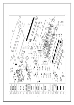
Page 21: ...25 EXPLODED DRAWING ...

Page 22: ...26 ...

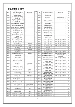
Page 23: ...nder 1 D16 Top signal wire Wire length 450mm 1 B06 Locking pin spring φ12 41 2 D17 Middle signal wire 1 Wire length 600mm 1 B07 Front roller 1 D18 Middle signal wire 2 Wire length 1100mm 1 B08 Back roller 1 D19 Bottom signal wire Wire length 500mm 1 B09 6 Allen wrench 1 D20 Instant speed top signal wire Wire length 450mm 1 B10 Pull pin φ9 23 5 2 D21 Instant incline top signal wire Wire length 450m...

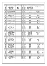
Page 24: ...5 2 C15 Handrail label holder 2 E14 Bolt M5 10 4 C16 Matrix plate 1 E15 Flat washer 8 6 C17 Small roller bracket 2 E16 Big washer φ8 φ22 2 0 4 C18 Handrail foam L 1 E17 Big washer φ10 2 C19 Handrail foam R 1 E18 Big washer φ5 4 C20 Left front cover 1 E19 Spring washer 8 6 C21 Right front cover 1 E20 Lock washer 10 2 C22 Back cover 2 E21 Lock washer 8 7 C23 Left top side rail 1 E22 Nut M10 2 C24 Ri...

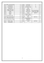
Page 25: ...ed base 1 F03 Single wire Wire length 500mm 1 C46 Button 2 F04 Ground wire Wire length 350mm 1 C47 Button 1 F05 Screw ST4 2 12 4 C48 Button 1 G01 Wireless receiver 1 C49 Anti rotating washer 2 G02 HRC connecting wire 1 C50 Motor rubber washer 1 G03 Screw ST2 9 6 0 4 C51 Turning knob overlay 1 H01 Bluetooth module 1 C52 Console panel overlay 1 H02 Bluetooth connecting wire 1 C53 Button overlay 1 H0...

Page 26: ...GARLANDO SPA Via Regione Piemonte 32 Zona Industriale D1 15068 Pozzolo Formigaro AL Italy www toorx it info toorx it ...

Reviews: