Digit “2” = Zone 2
Digit “3” = Zone 3
Digit “4” = Zone 4
Digit “5” = Zone 5
Digit “6” = Zone 6
Digit “7” = Tamper or Panic from wireless accessories
Digit “9” = Panic button or Tamper on Control Panel was activated
•
To clear the Alarm Activation Memory, follow the steps below:
1)
Enter the
P
key
2)
Enter your new (or default) Passcode:
x
x
x
x
3)
Wait until the LED displays “P”
4)
Enter the
#
key (Command Code for this function)
5)
The LED will display “0” “0” to confirm the programming is successful
ADVANCED PROGRAMMING
This section is for advanced programming options and should only be used in the following cases:
•
The Site Code default was incorrect and does not match with the other Site Code settings
•
There are two similar systems within wireless signal range of each other
•
You would like to change the Site Code or Zones for extra security or other reasons
Setting the Site Code
In order to prevent from any unauthorized attempt to operate or disarm your system, it’s necessary
to configure your system to accept radio signals only from your own system accessories. This is
done by setting a series of DIP switches in all accessories (except the control panel) to the same
ON/OFF combination.
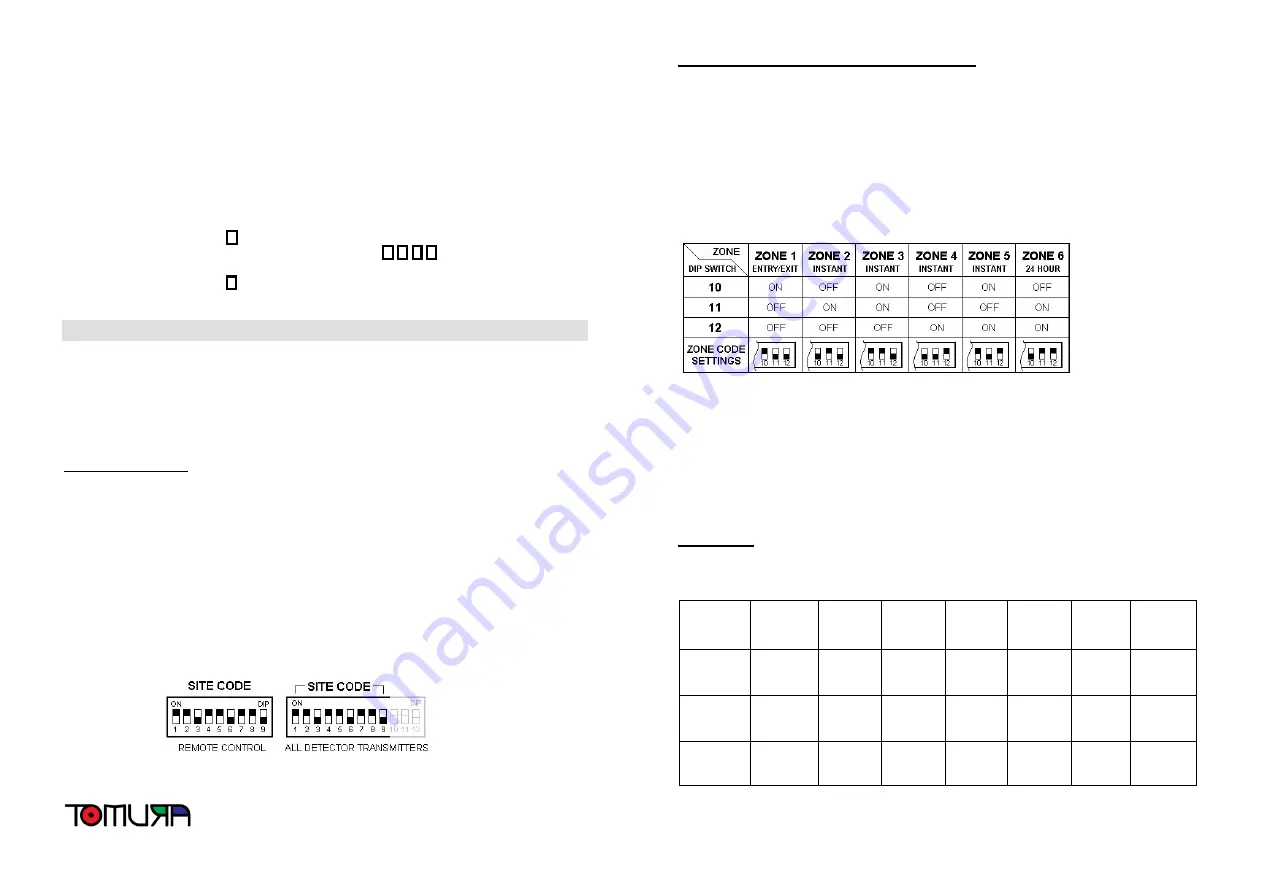
The Site Code is set up by moving each of the 9 DIP switches in each accessory to the same
randomly selected ON/OFF sequence. When setting the DIP switches, ensure that each switch
‘clicks’ fully into position. Use the tip of a ball pen or a small screwdriver to move each switch in
turn. The figure below shows a Site Code example setting for the Remote Controls and all
detector transmitters. If you change the Site Code, you must re-program the Control Panel to
match the same code. This can be accomplished by following the procedure in “Step 7 – Code
Learning from Remote Control” in the Simple Step-by-Step Programming section.
Setting the Sensors/Transmitters to Specific Zones
This system has Six “Zones” plus a Panic/Tamper Zone, each of which can be triggered during
various alarm situations (see Active Zones below). These Zones can help you to pinpoint which
sensor/transmitter was triggered in an alarm situation or system notification. The factory default
Zone settings are fine for most users, but can be changed if necessary.
The wireless detector transmitters use twelve DIP Switches to set the Site Code and Zones
(1-9 for Site Code; 10-12 for Zone). The settings for switches 10 through 12 will determine the
Zone that a sensor will trigger when an alarm is activated, battery is low and so on.
The figure below shows the DIP Switch settings for each particular Zone.
* You should normally set your Door/Window sensor to Zone 1 as this is the only zone that
allows sufficient time to disarm you system when entering the premises.
* Zone 2 to Zone 5 are Instant Zone which activate an alarm instantly when system was set to
Full Arming (Away) mode.
* Detectors/sensors set to Zone 2 & Zone 3 will not activate the system when set into Partial
Arming (At-Home) mode.
* You should normally set the Wireless Smoke (Fire, or Gas) Detectors to Zone 6 which will
activate the system instantly 24 hours a day even the system is set to Disarming mode.
Active Zones
The table below shows which Zones are active in the various modes that the system can be set to.
MODE
ZONE 1
(Entry/Exit)
ZONE 2
(Instant)
ZONE 3
(Instant)
ZONE 4
(Instant)
ZONE 5
(Instant)
ZONE 6
(24-HR,
Smoke,
etc.)
PANIC/
TAMPER
(24-HR)
Full
Arming
Mode
Active
Active
Active
Active
Active
Active
Active
Partial
Arming
Mode
Active
Not
Active
Not
Active
Active
Active
Active
Active
Disarming
Mode
Not
Active
Not
Active
Not
Active
Not
Active
Not
Active
Active
Active


