Toa WT-4800 Operating Instructions Manual Download Page 8

8

7. HOW TO CHECK AND DEAL WITH INTERFERENCE 

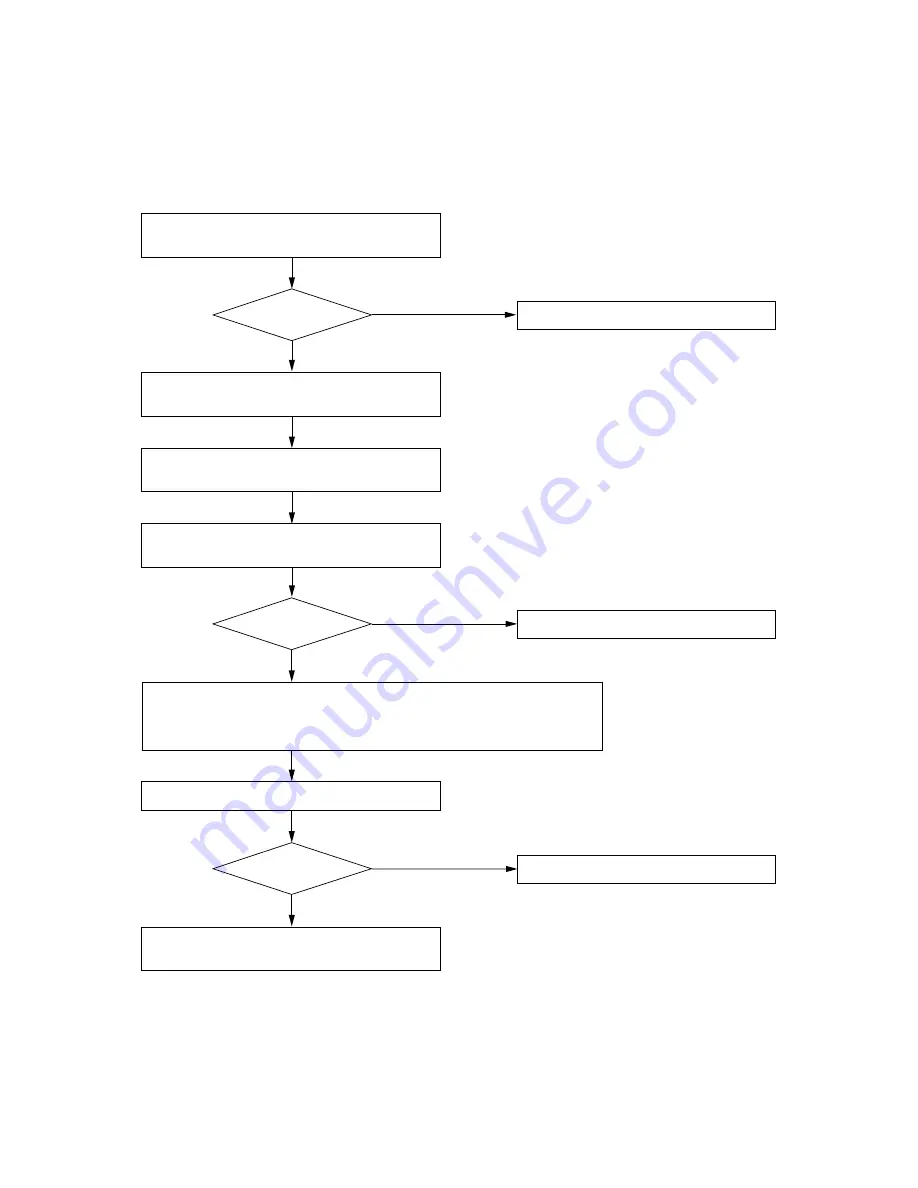
7.1. Order of Actions (Action Flowchart) 

Place unit in RF check mode and check 
signal condition of the channel.

[No]

Any 

interference?

[Yes]

[No]

Any 

interference?

[Yes]

[No]

Any 

interference?

[Yes]

Change bank/channel numbers to those of 
idle channels.

It is convenient to use "Channel Check" 
when selecting idle bank/channel numbers.

Place unit in RF check mode for a while and 
check signal condition of the channel. 

Adjust squelch control to limit service area.

When radio interference is still encountered, 
consult shop from where unit was purchased.

Refer to p. 9 "7.2. RF Check Mode Setting."

Refer to p. 9 "7.4. Squelch Adjustment."

Use as is.

Refer to p. 6 "6.2. Channel/Bank Number Settings."

Refer to p. 9 "7.3. Channel Detection."

Use as is.

Use as is.

Most interference can be avoided by operations above. If interference 
is still encountered, select channel having relatively less interference 
using RF check switch, then continue following operations.

Summary of Contents for WT-4800

Page 1: ...ES 4 4 HANDLING PRECAUTIONS 4 5 NOMENCLATURE AND FUNCTIONS Front 5 Rear 5 6 OPERATION 6 1 Basic Operation 6 6 2 Channel Bank Number Settings 6 6 3 Microphone Sensitivity Adjustment 7 7 HOW TO CHECK AN...

Page 2: ...y switch off the power disconnect the power supply plug from the AC outlet and contact your nearest TOA dealer Make no further attempt to operate the unit in this condition as this may cause fire or e...

Page 3: ...shock When the Unit is in Use Do not place heavy objects on the unit as this may cause it to fall or break which may result in personal injury and or property damage In addition the object itself may...

Page 4: ...temperature When installing keep the unit as far away as possible from fluorescent lamps digital equipment personal computers and other equipment which generate high frequency noise Only the same ban...

Page 5: ...NC For the wireless system covering a relatively narrow area use the supplied two rod antennas one of which should be mounted at a 45 angle outwards from a vertical line 9 Antenna input B For signal r...

Page 6: ...e SET FREQUENCY indication is first displayed The display then cycles through the SET BANK SET SQ LEVEL Rf CHECK CHANNEL CHECK INDEX and END SETTING indications with each subsequent depression of the...

Page 7: ...nsitivity Adjustment Although the audio level is preset by the factory it can be adjusted depending on the user s voice level Step 1 Holding the microphone body rotate the microphone grip counterclock...

Page 8: ...k mode for a while and check signal condition of the channel Adjust squelch control to limit service area When radio interference is still encountered consult shop from where unit was purchased Refer...

Page 9: ...ondition that a radio signal to be received is a certain level of signal strength This strength level can be varied by means of the squelch control 7 4 1 Squelch Level Setting Step 1 Press the Menu En...

Page 10: ...e input MIC LEVEL To amplifier microphone input LINE LEVEL To amplifier line input MIC LEVEL To amplifier microphone input Balanced Unbalanced Accessory or Wall mounted wireless antenna YW 4500 option...

Page 11: ...nector supplied with MB WT2 When mounting two WT 4800 units use an optional mounting kit MB WT2 10 FIRMWARE VERSION Step 1 Press the Menu Enter key for over a second to place the unit in setting mode...

Page 12: ...tor balanced Mixing Input 20 dB 10 k Phone jack unbalanced Antenna Input 75 BNC phantom powering for antenna 9 V DC 30 mA max Antenna Output 75 BNC Gain 0 dB Receiving Sensitivity Better than 80 dB S...

Reviews: