


6
6. OPERATION
6.1. Basic Operation
Step 1. Turn power on, and the power indicator lights.
Step 2. Set the microphone switch to the ON position.
The reception lamp lights when the tuner receives the same frequency signal.
Step 3. Adjust the volume control.
The output level increases as the control is rotated clockwise, and decreases as rotated
counterclockwise.
6.2. Channel/Bank Number Settings
6.2.1. Channel (frequency) setting
Step 1. Press the Indication Selector key (RF/AF/NEXT key) until the screen displays the channel
(frequency).
Step 2. Pressing the Menu/Enter key continuously for over a second will place the unit in setting mode, and
the "SET FREQUENCY" indication is first displayed. The display then cycles through the "SET
BANK," "SET SQ LEVEL," "Rf CHECK," "CHANNEL CHECK," "INDEX," and "END SETTING"
indications with each subsequent depression of the Menu/Enter key.
Step 3. Press the Indication Selector key when the "SET FREQUENCY" indication is displayed. The screen
displays the ">>" indication representing the setting mode, which is followed by the currently-set
channel number and frequency. (Example: >> 03 805.000MHz). Subsequent depression of the
Indication Selector key cycles the display through 16 channel numbers (frequencies).
Step 4. Select the desired frequency, then press the Menu/Enter key. The ">>" indication will disappear to
register the setting and only the channel number will be displayed together with the frequency.
1
3
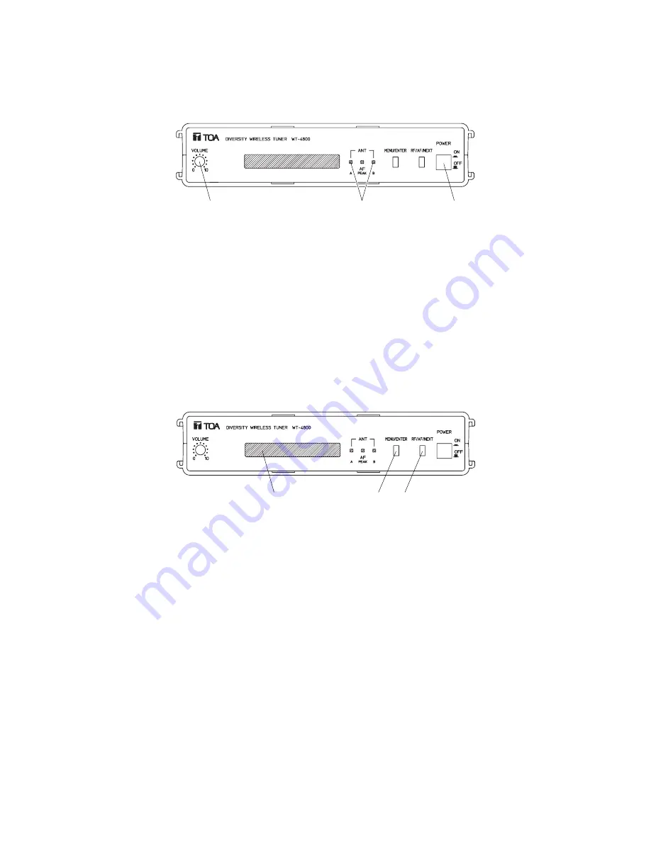
Reception lamps
Screen
Menu/enter key
Indication selector key


