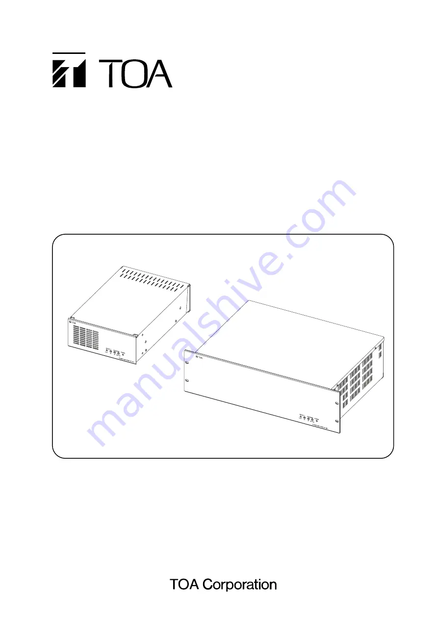
Toa VP-1061 Operating Instructions Manual Download Page 1

POWER AMPLIFIERS

VP-1061 (60 W)
VP-1121 (120 W)
VP-1241 (240 W)
VP-1361 (360 W)

Thank you for purchasing TOA's Power Amplifier.
Please carefully follow the instructions in this manual to ensure long, trouble-free use of your equipment.

OPERATING INSTRUCTIONS

Summary of Contents for VP-1061

Page 1: ...1 60 W VP 1121 120 W VP 1241 240 W VP 1361 360 W Thank you for purchasing TOA s Power Amplifier Please carefully follow the instructions in this manual to ensure long trouble free use of your equipment OPERATING INSTRUCTIONS ...

Page 2: ...IONS 6 1 Front 5 6 2 Rear 6 7 RACK MOUNTING 8 8 REMOVABLE TERMINAL PLUG CONNECTION 9 9 CONNECTIONS 9 1 Connecting to an AC Power Source 10 9 2 Connecting to a DC Power Supply 10 9 3 Speaker Connection 10 9 4 Attenuator Connection 10 10 DIMENSIONAL DIAGRAM 10 1 VP 1241 VP 1361 11 10 2 VP 1061 VP 1121 11 11 SPECIFICATIONS 12 Accessories 12 Optional Products 12 ...

Page 3: ...s into the unit If the unit falls or the unit case breaks If the power supply cord is damaged exposure of the core disconnection etc If it is malfunctioning no tone sounds To prevent a fire or electric shock never open nor remove the unit case as there are high voltage components inside the unit Refer all servicing to qualified service personnel Do not place cups bowls or other containers of liqui...

Page 4: ...t s cover Doing so may cause heat to build up inside the unit and result in fire Avoid installing the unit in humid or dusty locations in locations exposed to the direct sunlight near the heaters or in locations generating sooty smoke or steam as doing otherwise may result in fire or electric shock When unpacking or moving the unit be sure to handle it with two or more persons Falling or dropping ...

Page 5: ...iority input 18 volume Turn the control clockwise to increase the volume and counterclockwise to decrease it 5 Priority input Fault indicator Lights green while the Priority control input terminals 17 are shorted Lights red when the fault detection circuit is activated Operates when the YA 1000A is mounted VP 1061 VP 1121 5 INSTALLATION PRECAUTIONS Avoid using the power supply cord other than the ...

Page 6: ...to the unit Connecting the case terminal to the functional ground terminal of the external equipment may reduce the hum noise A ground lift jumper is factory set between the Case and Circuit terminals When this jumper is removed the circuit ground can be electrically disconnected Note This ground is not for protective ground 10 24 V DC Power input terminals Connect to 24 V DC power supply 11 Emerg...

Page 7: ...r the one through the Program input 15 while the Priority control input 17 terminals are shorted 19 Priority control output terminals These terminals are internally connected in parallel to the Priority control input terminals 17 20 Priority output terminals These terminals are internally connected in parallel to the Priority input terminals 18 Connecting these terminals to the other amplifier s i...

Page 8: ... Secure the Joint Bracket supplied with the MB 25B J to the bottom sides of the units using 2 supplied tapping screws 3 x 8 Step 2 Secure the supplied joint bracket to the units rear panels using 2 supplied tapping screws 3 x 8 Step 3 Secure the supplied joint bracket to the units top panels using 2 supplied tapping screws 3 x 8 Step 4 Attach one Mount Bracket to the side of each unit as shown at ...

Page 9: ...sive rise in joint temperatures Usable cables of AWG 16 28 Cable end treatment Shielded cable 7 mm 20 mm When mounting 2 or more units in an equipment rack be sure to mount a perforated panel larger than 1U size above every 2 stacks of amplifiers as shown in the figure 1U size 44 5 mm standard size It is recommended that a supporting runner be installed to the rack so that the unit can be easily d...

Page 10: ...broadcast attenuators can be connected using either of the following two methods 3 wire system 4 wire system Use the DC power cable of AWG 16 or thicker VP 1061 and VP 1121 or AWG 12 or thicker VP 1241 and VP 1361 Also be sure to firmly screw the cable to the terminal Failure to do so may cause the cable to generate heat possibly resulting in fire 9 2 Connecting to a DC Power Source When using a 2...

Page 11: ...11 10 DIMENSIONAL DIAGRAMS 10 1 VP 1241 VP 1361 Unit mm 483 6 465 37 7 57 2 132 6 337 8 320 5 10 2 VP 1061 VP 1121 210 88 4 338 7 321 5 ...

Page 12: ...4 W 19 W 21 W 37 W DC at rated output 4 5 A 8 2 A 14 6 A 20 9 A DC no signal 0 1 A 0 1 A 0 4 A 0 5 A Rated Output 60 W 120 W 240 W 360 W Input 2 Program inputs parallel 0 dB 20 kΩ balanced 2 Priority inputs parallel 0 dB 20 kΩ balanced Impedance 167 Ω 83 Ω 42 Ω 28 Ω S N Ratio 80 dB or more Total Harmonic Distortion 1 or less at rated output f 1 kHz Frequency Response 80 Hz 16 kHz 3 dB at 1 3 rated...

Reviews: