Toa MX-101 Operating Instructions Manual Download Page 9

Specifications

MIXER SECTION

Frequency  Response

+ 1,  -3dB 30Hz~20kHz (input LEVEL at "5" position)

Total Harmonic Distortion

0.05% +4dB* at 1kHz.

Hum and Noise (Open)

Equivalent Input Noise

Equivalent Input Noise
All level Controls Minimum
SYSTEM Master at MAX and all

input level controls minimum

SYSTEM Master at MAX and one

input level control at Max

-132dB* (20Hz~

20kHz)

-134dB*  (IHFA)
-105dB*  (IHFA)
-87dB*  (IHFA)

-70dB*  (IHFA)

Maximum Voltage Gain

INPUT to SYSTEM out
INPUT to FB out
TAPE to SYSTEM out

Equalization

50Hz ±15dB Shelving
2kHz ±15dB Peaking
15kHz  ±15dB Shelving

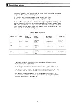
INPUT  SPECIFICATIONS

CONNECTION

CH1

CH4

TAPE

INPUT

LOW Z

HIGH Z

ACTUAL
LOAD
IMPEDANCE

OPEN

FOR USE
WITH
NOMINAL

MICRO-
PHONES

OR

LOWER IMP
LINES

OR

LOWER IMP
LINES

SENSITIVITY*

(PGM OUTPUT

LEVEL +4dB)

-60dB(0.78mV)

-35dB(13.8mV)

-10dB(245mV)

CONNECTOR

XLR TYPE

PHONE  JACK

RCA PIN JACK

OUTPUT  SPECIFICATIONS

CONNECTION

SYSTEM

FB

ACTUAL
SOURCE
IMPEDANCE

FOR USE WITH
NOMINAL

OR  HIGHER

IMP LINES

OR  HIGHER

IMP LINES

OUTPUT  LEVEL*

NOMINAL

+4dB(1.23V)

+4dB(1.23V)

MAX  BEFORE
CLIP

+ 20dB(7.75V)

+ 20dB(7.75V)

CONNECTOR

PHONE JACK

PHONE JACK

POWER  AMPLIFIER  SECTION

Frequency  Response

+ 0 -1dB 15Hz to 30kHz (75 W RMS 

)

Rated Power & Load

75W RMS 

57W RMS

Power Output at Clipping

1% THD. 1kHz
80W RMS 

60W RMS

Total Harmonic Distortion

Less than 0.1% (100mW~75W RMS. 20Hz~20kHz.
Typically below 0.05%

Compresser Dynamic Range

Greater than 26dB

Hum and Noise

At least 100dB S/N ratio. 20Hz~20kHz
At least 108dB S/N ratio IHF-A weighted

Damping Factor

200 (1kHz

Output Connector

Phone Jack × 2

Power Requirement

182 W

Dimensions

460(W) × 171(H) × 248(D) (18.11 × 6.73 × 8.91) ins.

Weight

7.5 Kg (16.5 Ibs)

*0dB is referenced to 0.775V RMS.

*Specifications are subject to change without notice.

64dB
64dB
14dB

— 8 —

All manuals and user guides at all-guides.com

Summary of Contents for MX-101

Page 1: ...POWERED MIXER Operating instruction Manual Model MX 101 Toa Electric Co Ltd KOBE JAPAN All manuals and user guides at all guides com a l l g u i d e s c o m ...

Page 2: ...ms 9 Appearance 9 Precautions 1 XLR Type Audio Connector The connectors are wired as follows The pin 1 is ground shield the pin 2 cold low minus the pin 3 hot high plus 2 Description of components and functions on the MX 101 Various descriptions are applied depending on each manufacturer In our Operating and Instruction Manual explanation of components and func tions is made according to our usage...

Page 3: ...control send The master control section features a 3 band equalizer a high quality 2 spring reverb RCA tape inputs and master volume controls for System level Foldback and Reverb return to both The power amp features protection circuitry and autocomp compressor both with indicator LED s Features 1 Four input channels 2 57 watts into 8 ohms 75 watts into 4 ohms 3 3 band EQ 4 Auto Comp compression u...

Page 4: ...signal and rotating the control counter clockwise decreases the high frequency signal The center position provides flat au dio response Tape Input Jacks TAPE These RCA pin jacks are wired in parallel with an input level of 10dB PowerIndicatorLED POWER The indicator LED lights when the power switch is on Power Amp Protection Indica tor PROTECT The indicator LED lights if the power amplifier output ...

Page 5: ...he ground pin should not be removed under any circumstances If the MX 101 must be used without prop er grounding facilities a suit able grounding adapter should be utilized Operation of the MX 101 with proper grounding techniques will result in less system noise and greatly reduced shock hazard Warning To avoid possible equipment damage and or personnel in jury the fuse should always be replaced w...

Page 6: ... From FB OUT Jack on Rear Panel From Speaker Jack on Real Panel Low Z input should be connected with low impedance 50 ohm 600 ohm microphones Line Out KEYBOARD CASSETTE TAPE DECK for playback Line Out MUSICAL INSTRUMENT 5 All manuals and user guides at all guides com a l l g u i d e s c o m ...

Page 7: ...IONS CONNECTION CH1 CH4 TAPE INPUT LOW Z HIGH Z ACTUAL LOAD IMPEDANCE OPEN FOR USE WITH NOMINAL MICRO PHONES OR LOWER IMP LINES OR LOWER IMP LINES SENSITIVITY PGM OUTPUT LEVEL 4dB 60dB 0 78mV 35dB 13 8mV 10dB 245mV CONNECTOR XLRTYPE NC3FPP PHONE JACK RCA PIN JACK Sensitivity is the level required to produce a program out level of 4dB 0dB is referenced to 0 775V RMS All XLR Type connectors are elec...

Page 8: ...Block and Level Diagrams BLOCK DIAGRAMS LEVEL DIAGRAM 7 All manuals and user guides at all guides com ...

Page 9: ...mV 10dB 245mV CONNECTOR XLRTYPE PHONE JACK RCA PIN JACK OUTPUT SPECIFICATIONS CONNECTION SYSTEM FB ACTUAL SOURCE IMPEDANCE FOR USE WITH NOMINAL OR HIGHER IMP LINES OR HIGHER IMP LINES OUTPUT LEVEL NOMINAL 4dB 1 23V 4dB 1 23V MAX BEFORE CLIP 20dB 7 75V 20dB 7 75V CONNECTOR PHONE JACK PHONE JACK POWER AMPLIFIER SECTION Frequency Response 0 1dB 15Hz to 30kHz 75 WRMS RatedPower Load 75W RMS 57W RMS Po...

Page 10: ...ics Diagrams HIGH Z IN INPUT EQ 3 BAND EQ POWER AMP POWER BAND WIDTH POWER AMP T H D vs POWER OUTPUT POWER AMP COMPRESSOR REVERBERATION FREQUENCY RESPONSE Appearance 9 All manuals and user guides at all guides com ...

Page 11: ...ToaElectricCo Ltd KOBE JAPAN Printed in Japan 133 02 884 9 All manuals and user guides at all guides com a l l g u i d e s c o m ...

Reviews: