DISASSEMBLING INSTRUCTIONS
IR-200M, IR-300M Y
6
6
ADJUSTMENT PROCEDURE
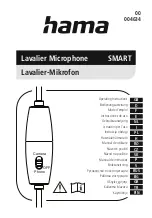
7. Remove 3 screws circled on the photo, then remove the windscreen frame, switch knob, switch
knob fixing clamp, and LED light.
8. Remove 2 screws securing the windscreen frame to the neck joint. Detach the lower filter, then
remove the microphone element assembly and shock mount.
9. Detach the upper filter inserted between the windscreen net and microphone element holder using
tweezers.
10. When reassembling, proceed the steps in reverse order.
Switch knob fixing clamp
Switch knob fixing clamp
Switch knob fixing clamp
LED light.
LED light.
LED light.
Windscreen frame
Windscreen frame
Windscreen frame
Switch knob
Switch knob
Switch knob
LED light.
LED light.
LED light.
10
9
8
Windscreen frame
Windscreen frame
Windscreen frame
Switch knob fixing
Switch knob fixing
clamp
clamp
Switch knob fixing
clamp
Neck joint
Neck joint
Neck joint
Screws
Screws
Screws
Windscreen frame
Windscreen frame
Windscreen frame
Lower filter
Lower filter
Lower filter
Shock mount
Shock mount
Shock mount
Microphone
Microphone
element assembly
element assembly
Microphone
element assembly
1
5
3
4
6
Neck joint
Neck joint
Neck joint
Windscreen
Windscreen
frame
frame
Windscreen
frame
Upper filter
Upper filter
Upper filter
Windscreen frame
Windscreen frame
Windscreen frame
1
2
Upper filter
Upper filter
Upper filter
Windscreen frame
Windscreen frame
Windscreen frame
• Measuring instruments to be used
· Modulation analyzer
: Band-width
: 1.5 - 30 MHz or more
(Deviation meter, Frequency counter)
Zi = 50
Ω
· Audio analyzer
: Band-width
: 20 Hz - 20 kHz or more
(Audio frequency generator and Distortion meter) Output impedance : 600
Ω
Input impedance
: 100
Ω
or more
· Oscilloscope: Band-width
: 20 MHz or more
· Regulated DC power supply
: 0 - 5 V DC
· DC ammeter
: Full scale
: 1 A or more
· DC voltmeter
: Full scale
: 10 V or more
· Spectrum analyzer
: Band-width : 1.5 - 30 MHz or more, Zi = 50
Ω
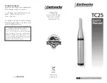
• Connection diagram
Regulated
DC power
supply
Input
DC ammeter
Output
Oscilloscope
Spectrum
analyzer
PCB unit for the
IR-200M/300M
(Each PCB must be
connected as is actually used.)
Audio analyzer
AF oscillation output
600Ω
Over 10 μF
Ceramic
capacitor
1μF 16V
AF input
DC
Power
RF output
Brightness
modulation level
+
Input
Modulation analyzer
AF output
RF input
DC voltmeter
Note:
Use shielded cables for AF line and 50 Ω coaxial cables for RF line.
Current probe
PCB unit to be supplied as a service part is calibrated at the factory before shipment and further
adjustment is not required.
Adjust and check your microphone once the parts related to adjustment points on the PCB have been
replaced.
ADJUSTMENT PROCEDURE