background image

Feedback  Prevention

When the overall gain of a sound system is increased, feedback will  occur  at  frequencies
where the system  response has peaks.  Suppose the system has  an uneven frequency
response like that shown in the following diagram. The frequency  at which feedback will
occur when gain is increased is about 500Hz. In this case, feedback may be prevented by
attenuating levels at 500Hz by 5dB to 7dB with the E 111/112. If the overall gain is again
gradually increased, feedback  will occur next at about 125Hz. It may be stopped by
attenuating the  levels 2dB to 3dB at that frequency. In this procedure,  sufficient gain in

the sound system is obtained before feedback.  When the equalizer is used for this
purpose, the bandwidth  controls are turned anticlockwise to prevent affecting other
frequencies not needed for equalizing.  In addition, the frequencies at which feedback will
occur are  not necessarily  the same for each system and environment, therefore the

equalizer is  more  effective if the center  frequency  control is  made use of to precisely
match center frequencies with the frequencies at which feedback occurs.

Room Equalization

In a sound reinforcement system for a room, the clarity of sound can be  adversely affected
by the  room frequency  response including standing waves  (room resonances), reflections
of sound,  and relations between  direct and indirect sound.
The E 111/112 are effective tools to equalize the room frequency response to a flat
response and improve sound clarity.
The effective use of the equalizer sliders,  center  frequency controls,  and bandwidth
controls make it easy to equalize various frequency  responses in rooms to be flat.
For example,  suppose that there is  a room f r e q u e n c y  response as shown below.

The equalizer sliders,  center  frequency  controls  and bandwidth controls are set  as  shown
below.

The response of those frequencies at which the  corresponding equalizer sliders are set to
0dB positions  will remain unchanged regardless of the positions of the center frequency
controls  and  bandwidth  controls. The overall response  after equalization will  then be as
follows.

— 9  —

Frequency

Sound

Pressure

 Level

Sound

 Pressure

 Level

Before equalization

Frequency  response
of equalizer

Frequency response
after  equalization

Frequency

Applications

Summary of Contents for E 111

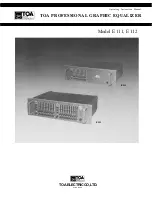
Page 1: ...Operating Instruction Manual TOA PROFESSIONAL GRAPHIC EQUALIZER Model E 111 E 112 E 112 TOA ELECTRICCO LTD KOBE JAPAN E 111 ...

Page 2: ...ly and 220 240V AC operation with a voltage selector The voltage selector on the rear panel of the 220 240V version should be checked for proper setting prior to operation as improper setting causes trouble The voltage selector is set for 240V operation at the factory 3 Do not operate the equalizer from power mains which exceeds the indicated mains voltage by more than 10 4 Do not expose the equal...

Page 3: ...unction provides complete equalization bypass in the event of loss of AC power and an output muting function suppresses turn on turn off transients A smoked plastic security cover is included with the E 111 or E 112 to guard against accidental disturbance or intentional tampering when used in fixed installations Inputs and outputs are transformer isolated and balanced with both XLR and 1 4 stereo ...

Page 4: ...B Rated Output Level 4dB Maximum Input Level 24dB at 1kHz Maximum Output Level 24dB with 600 ohm load Input Impedance 10k ohms Output Impedance 600 ohms High Pass Filter 40Hz 12dB octave Low Pass Filter 12kHz 12dB octave Hum and Noise 103dB EQ IN all sliders at 0 position A curve by IHF Protect AC fail safe Power Consumption E 111 10W E 112 19W Dimensions 483 W l33 H 370 L mm 19 W 5 25 H l4 6 L in...

Page 5: ...ESPONSE Each slider is set at a max position FREQUENCY RESPONSE ex 1kHz slider FREQUENCY FREQUENCY BANDWIDTH CONTROL ex 1kHz slider CENTER FREQUENCY CONTROL ex 1kHz slider FREQUENCY FREQUENCY 4 Performance Graphs ...

Page 6: ...of 12dB per octave when IN Equalizer switch Placing the switch in the IN position causes the equalizer LED indicator to turn on and provides the frequency response adjusted with the EQ sliders bandwidth controls and centre frequency controls With the switch in the OUT position the equalizer LED goes out and the frequency response is flat just as the EQ sliders allow for a flat response when set to...

Page 7: ...the fuse of same type and capacity as are instructed Power inlet An accessory power cord connects here A use of the U shaped clamp supplied with the equalizer by inserting it into the holes provided above and below the power inlet is recommended to prevent accidental disconnection of the power cord Ground lift switch The switch is used to avoid earth loop that causes hum noise when the equalizer E...

Page 8: ... loops may cause hum and noise if care is not taken during connection An increase in noise from ground loops may be minimized by breaking the ground loop Generally the chassis ground of the signal line should be broken as shown below Rack cabinet Main AC Ground When a Y cord is used shorten the wiring to minimize noise Ground lift switches are provided on the rear of the E 111 112 Sliding the grou...

Page 9: ...quency band is continuously variable within a range of one octave between 0 7fc and 1 4fc Thus the overall frequency response may be delicately adjusted For example if the 1kHz center frequency control has a 12dB boost the frequency response looks like that of curve 1 If the center frequency control is turned anticlockwise the response will be like curve 2 while in the case of it being turned full...

Page 10: ...f to precisely match center frequencies with the frequencies at which feedback occurs Room Equalization In a sound reinforcement system for a room the clarity of sound can be adversely affected by the room frequency response including standing waves room resonances reflections of sound and relations between direct and indirect sound The E 111 112 are effective tools to equalize the room frequency ...

Page 11: ...ce Piano Acoustic Piano Electric Organ Violin Brass instruments Bass drum Snare drum Tom Tom Floor Tom Hi Hat Cymbal overhead Talk Box Bass strings resonate between 70 to 120Hz body around 300Hz Avoid boosting these to stop feedback 3kHz and 5kHz gives great clarity Resonances differ depending on type Good full sounds around 300 to 500Hz Clarity at 3kHz Extreme lows are at 60 to 90Hz Pick or pluck...

Page 12: ...TOA ELECTRICCO LTD KOBE JAPAN Printed in Japan 133 02 688 3 ...

Reviews: