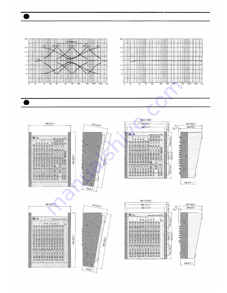
* Dimensions with brackets
D-5.5E
Appearance
D-5.5
FREQUENCY RESPONSE
INPUT EQ CHARACTERISTICS
Characteristics Diagrams
FREQUENCY
LEVEL
— 20 —
Page 1: ...ToaElectricCo Ltd Model D 5 5 D 5 5E ELECTRONIC MUSIC MIXER Operating Instruction Manual KOBE JAPAN...
Page 2: ...D 5 5E are designed to operate on local AC 50 60Hz Mains 10 2 XLR Type Audio Connector The connectors are wired as follows The pin 1 is ground shield the pin 2 cold low minus the pin 3 hot high plus...
Page 3: ...groups and Stereo L R also feature dual color signal prescence clip LED indicators an on off switch with orange LED writing block 60 mm fader and cue switch The D 5 5 rear panel features an RCA tape...
Page 4: ...t fader 2 Aux sends selectable pre EQ and fader post EQ pre fader post EQ and fader Mono reverb send and mono effects send both are post EQ and fader Headphones output with level control Push button c...
Page 5: ...computer type connector Input Channel Connections Separate pre and post accessory patch points RCA Direct Output RCA Source inputs 1 4 phone jack and electronically balanced XLR with individually swit...
Page 6: ...ls of the associated inputs are as follows a Mic input 60dB b Tape input 20dB c Phono input 50dB Input channels 7 and 8 only The trim control and input level selector of each channel should be properl...
Page 7: ...oup assign control to the group 3 and 4 busses providing equal output to the group 3 and 4 busses at the detent center position Rotating the pan control counter clockwise decreases the amount of the s...
Page 8: ...ses the signal level of the aux 1 return keeping the original level of the aux 2 return signal Return Signal Select Switch REV EFF AUX 1 AUX 2 This switch selects either the REV EFF return signals or...
Page 9: ...ssigns the signal from the effects return to the stereo L and R busses Cue Switch CUE The switch permits monitoring the signal prior to the effect return level control Sum Select Switch SUM SLECT PRE...
Page 10: ...switch is off When the cue switch is on the control adjusts the corresponding cue signal When two or more of the cue switches are on the control adjusts the corresponding combined cue signals The cue...
Page 11: ...d with a nominal level of l0dB Input jack impedance is 10k ohms and output jack impe dance is 1k ohms The Accessory jacks allow signal processing and effect devices to be inserted into the signal path...
Page 12: ...gnal Peak LED Indicator SIG PEAK Input Level Selector PAD Input Trim Control TRIM High Equalizer Control HIGH Mid Equalizer Center Frequency Control MID FREQ Mid Equalizer Control MID LEVEL Low Equali...
Page 13: ...trol up to four other MIDI synths ten when using the D 5 5E and sixteen when using the two D 5 5E s Earth Terminal Balanced XLR Microphone Input MIC Phantom Power Switches PHANTOM 9 20 1 4 Phone Chann...
Page 14: ...Block Diagrams D 5 5 BLOCK DIAGRAM D 5 5E BLOCK DIAGRAM 15...
Page 15: ...D 5 5 LEVEL DIAGRAM Level Diagrams D 5 5E LEVEL DIAGRAM 16...
Page 16: ...PIN JACK RCA PIN JACK RCA PIN JACK PHONE JACK PHONE JACK 0dB is referenced to 0 775V RMS Accessory D 5 5E ONLY BUSS LINK CABLE 6ft 1 0dB is referenced to 0 775V RMS Specifications are subject to chang...
Page 17: ...the side panels 3 The rear panel and blank panel should be inter changed to allow for easy connection when the D 5 5 and D 5 5E are rack mounted a Remove the rear panel corner frame and blank panel b...
Page 18: ...EQ controls will not affect the on stage monitor mix This is particularly desirable when the input source is a microphone Since an on stage monitor system is normally operated near acoustic feedback a...
Page 19: ...Dimensions with brackets D 5 5E Dimensions with brackets Appearance D 5 5 FREQUENCY RESPONSE INPUT EQ CHARACTERISTICS Characteristics Diagrams FREQUENCY FREQUENCY LEVEL LEVEL 20...
Page 20: ...ToaElectricCo Ltd KOBE JAPAN Printed in Japan 133 02 748 80...