Toa AM-CF1B Setup Manual Download Page 6

6

Name

Description

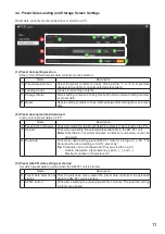
A Input gain display

Input gains are displayed numerically. 

Numerical values can be changed with the arrows to the right of each value. 

Initial setting: 0 dB

Tip: Linked to faders (C).

B Input level indicators Display input levels.

C Faders

Used to change input gains.

Tip: Linked to input gain display (A).

D Mute button

Click to mute corresponding input. Clicking again returns input to the previous 

level. 

E Reset button

Click to return all input adjustment settings to their initial settings. 

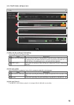
 (2) Output signal adjustment section (OUTPUT)

Perform settings related to output signals.

Settings for the following five types of output can be performed:

Speaker

USB

Bluetooth

CODEC

AUX

Name

Description

F EQ button

Performs equalization on both speaker and AUX outputs. Clicking this button 

opens the Equalizer Screen. (Se

p. 7

.)

G Output gain display

Output gains are displayed numerically. Numerical values can be changed 

using the arrows to the right of each value. 

Initial setting as follows:

Speaker, USB, CODEC, AUX: 0 dB

Bluetooth: –20 dB

Tip: Linked to faders (I).

H Output level indicators Display output levels.

I Faders

Used to adjust output gains.

Tip: Linked to output gain display (G).

J Mute button

Click  to  mute  corresponding  output.  Clicking  again  returns  output  to  the 

previous level. 

K Reset button

Click to return all output adjustment settings to their initial settings. 

 (3) APPLY button

Click this button after all settings on this screen are completed. Setting contents are applied. 

Summary of Contents for AM-CF1B

Page 1: ...u for purchasing TOA s Integrated Audio Collaboration System Please carefully follow the instructions in this manual to ensure long trouble free use of your equipment INTEGRATED AUDIO COLLABORATION SY...

Page 2: ...NGS 3 2 SYSTEM REQUIREMENTS 3 3 CONNECTIONS 4 4 SETTINGS 5 4 1 Settings Screen Switching 5 4 2 Mixer Screen Settings 5 4 3 How to Set the Audio Settings Screen 9 4 4 Preset Data Loading and Storage Sc...

Page 3: ...and outputs EQ parameter adjustment Settings for microphone sound collection Echo and noise cancellation settings Operation settings for control input and output terminals by contact input and output...

Page 4: ...2 168 14 1 The login screen is displayed Tip The IP address is factory preset to 192 168 14 1 Step 2 Enter a user name and a password The mixer screen is displayed Note Do not launch multiple web brow...

Page 5: ...o set microphone collection sound parameters echo cancellers and noise cancellers See p 9 3 Preset data loading and storage screen Preset Load Store Used to perform settings regarding the methods of l...

Page 6: ...n be performed Speaker USB Bluetooth CODEC AUX Name Description F EQ button Performs equalization on both speaker and AUX outputs Clicking this button opens the Equalizer Screen See p 7 G Output gain...

Page 7: ...on EQ curves are displayed depending on parameter settings 3 PEQ HPF setting section Used to set PEQ or HPF parameters Name Description A PEQ HPF selection Select the parameter type PEQ or HPF Initial...

Page 8: ...ting range and initial settings are shown in the table below Note Gain and Q cannot be set if LPF is selected in the PEQ HLPF selection Setting Ranges and Initial Settings Setting Item Setting Content...

Page 9: ...80 inch C X2 axis setting Set the distance from the microphone position in the direction of the X2 axis Setting range 0 to 300 cm 0 to 120 inch Initial setting 200 cm 80 inch D Shortest distance setti...

Page 10: ...H NLP Level setting Sets the setting level for Non Linear AEC processing Setting range Low Mid High Initial setting Mid I Microphone Gain setting Sets the output volume level of the beam steering micr...

Page 11: ...PC Name Description E File selection Browse Click when selecting the preset data file extension zip stored on the PC F Upload Click when uploading the selected preset data file to the AM CF1 unit Note...

Page 12: ...ings related to the configuration of the AM CF1 unit The following three configuration settings screens are available Click any one of the screen names shown in the screen below to switch the screen a...

Page 13: ...t Gateway Enter the AM CF1 unit s default gateway Initial setting 192 168 14 254 D APPLY button Click after setting entry completion The set network contents are applied 2 Administrator Setting Set th...

Page 14: ...gs screen 1 External control settings Control Set the input and output terminal operations to be activated by the contact input and output signals Name Description A Pull down menus 1 and 2 for contac...

Page 15: ...or OFF The selected mode is displayed in orange E Pull down menu for indicator mode selection during mute status Select from the pull down menu whether to turn on all multifunction LED indicators or...

Page 16: ...n The displayed time is not automatically updated B APPLY button Click after all necessary time settings are completed The set contents are applied 2 Firmware update Read the firmware update file from...

Page 17: ...d Click when uploading the selected configuration data file to the AM CF1 Unit Note Files that do not satisfy filename conditions see below cannot be uploaded G Download Click when downloading the AM...

Reviews: