Toa AM-CF1 Instruction Manual Download Page 15

15

9.4. bluetooth Pairing

 Step 1. Perform pairing operation on the connected peripheral device.

 Step 2. Hold down the Bluetooth Pairing switch for 3 seconds or more.

The Bluetooth indicator flashes. 

Bluetooth indicator

 Step 3. Confirm that the unit’s name is displayed on the peripheral device screen. 

 Step 4. Perform connection operation. 

Note

To cut off the connection while making the Bluetooth connection, hold down the Bluetooth Paring switch for 3 

seconds or more.

9.5. Volume Adjustment

The volume of sound output from the front panel speaker can be adjusted when in Normal Operation mode. 

While the volume is being adjusted, the current output volume setting state is displayed by the front panel-

mounted multifunction indicator. 
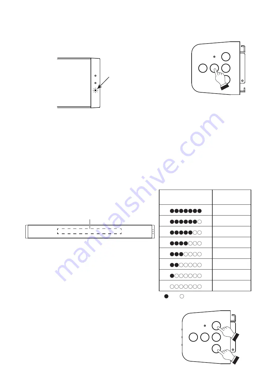
LED Lighting Status

Output Volume 

Setting Status

0 dB

−3 dB

−6 dB

−9 dB

−12 dB

−18 dB

−24 dB

−∞ dB

: Lit    : Unlit

Multifunction indicator

Follow the procedure below to adjust the output to an easy-to-hear volume:

 Step 1. Press the Volume Up switch to increase the volume.

The number of lit Multifunction Indicator LEDs increases by one 

with each depression of the switch. 

 Step 2. Press the Volume Down switch to decrease the volume.

The number of lit Multifunction Indicator LEDs decreases by one 

with each depression of the switch.

1

2

Summary of Contents for AM-CF1

Page 1: ...rated Audio Collaboration System AM CF1B AM CF1W Thank you for purchasing TOA s Integrated Audio Collaboration System Please carefully follow the instructions in this manual to ensure long trouble fre...

Page 2: ...7 8 Removable Terminal Plug Connection 12 8 SYSTEM SETTINGS 13 8 1 Overview of System Settings 13 8 2 System Requirements 13 8 3 Connections 13 9 OPERATION 14 9 1 Turning Power ON and OFF 14 9 2 Swit...

Page 3: ...e the unit is designed for indoor use do not install it outdoors If installed outdoors the aging of parts causes the unit to fall off resulting in personal injury Also when it gets wet with rain there...

Page 4: ...e that the use of other adapter may cause a fire If dust accumulates on the power supply plug or in the wall AC outlet a fire may result Clean it periodically In addition insert the plug in the wall o...

Page 5: ...Industry Canada To reduce potential radio interference to other users the antenna type and its gain must be so chosen that the equivalent isotropically radiated power e i r p is not more than that nec...

Page 6: ...g on the contents being displayed 1 When displaying the microphone input level When the AM CF1 unit is in use at a web conference etc only one LED facing in the direction of the speaker s voice lights...

Page 7: ...support 10BASE T or 100BASE TX When connecting the PoE extender use the following TPE 117GI made by TRENDnet 15 Power input terminal Connect a 12 V DC power source to this terminal For AC adapters us...

Page 8: ...o mount the AM CF1 unit to a wall Be sure to use the following wall mounting brackets and screws If hardware other than that mentioned below is used the unit could fall down potentially resulting in d...

Page 9: ...s removed in Step 1 Note Screws can be installed not only from the upward direction but also from the side or downward direction 7 CONNECTIONS 7 1 AC Adapter Connection Connect the AC adapter 1 to the...

Page 10: ...emove it straight away from the receptacle Do not pull on the cable to extract the plug as this may damage the connector OK NG Correct insertion direction Do not pull on the cable 7 4 AUX Input Connec...

Page 11: ...nections Use the supplied removable terminal plug 6 pins for connection Connect the control input and output blocks using 2 control lines from external control devices For removable terminal plug conn...

Page 12: ...is crushed possibly resulting in an excessive rise in joint temperatures Use cables of AWG 12 24 Terminal plug connections Step 1 Loosen the terminal screw then insert the cable Step 2 Retighten the t...

Page 13: ...or the multifunction indicators Saving and reading of the above setting data Maintenance Function Firmware update 8 2 System Requirements PC hardware requirements are as follows Display 1366 x 768 res...

Page 14: ...ion in progress Orange Normal operation mode Green Power OFF processing in progress Red Flashing blue green Blue Power standby mode Red Power OFF Extinguished 9 2 Switching between Power Standby and N...

Page 15: ...ont panel speaker can be adjusted when in Normal Operation mode While the volume is being adjusted the current output volume setting state is displayed by the front panel mounted multifunction indicat...

Page 16: ...e C terminal For example when terminals 1 2 have been allocated to Preset Memory Nos 1 2 in the contact input settings shorting individual terminals to the C terminal allows Preset Memory Nos 1 2 to b...

Page 17: ...Memory 1 2 to terminals The Preset Memory is accessed when its corresponding terminal is shorted to the C terminal If different Preset Memories are assigned to multiple terminals the last shorted term...

Page 18: ...Hold down the Power switch while confirming that the Power indicator is flashing blue green After approximately 30 seconds the Power indicator will light green and the USB connection indicator will li...

Page 19: ...che License 2 0 Apache 2 0 The 3 Clause BSD License The 2 Clause BSD License MIT License MIT Others We do not guarantee the operation of open source software itself but we do guarantee the functionali...

Page 20: ...ble terminal block 6 pins no voltage make contact relay contact output Network I F 10BASE T 100BASE TX RJ 45 Microphone Unidirectional electret condenser type Frequency Characteristics 20 Hz 20 kHz AU...

Reviews: